Cold-cathode ion source with a controlled position of ion beam

a technology of ion beam and cold cathode, which is applied in the direction of ion beam tubes, instruments, vacuum evaporation coating, etc., can solve the problems of low intensity of ion beam, inability to form ion beams of chemically active substances, and use of ion accelerating grids, etc., to improve the uniformity of ion current density, the effect of low cost and simple construction

Inactive Publication Date: 2000-03-14
ADVANCED ION TECH
View PDF4 Cites 117 Cited by
  • Summary
  • Abstract
  • Description
  • Claims
  • Application Information

AI Technical Summary

Problems solved by technology

A disadvantage of such a device is that it requires the use of ion accelerating grids and that it produces an ion beam of low intensity.
A disadvantage of the devices of such type is that they do not allow formation of ion beams of chemically-active substances when these ion beams are used for treating large surface areas.
Other disadvantages of the aforementioned devices are short service life and high non-uniformity of ion beams.
The ion source with a grid-like electrode of the type disclosed in U.S. Pat. No. 4,710,283 also has a number of disadvantages consisting in that the grid-like electrode makes it difficult to produce an extended ion beam and in that the ion beam is additionally contaminated as a result of sputtering of the material from the surface of the grid-like electrode.
A disadvantage of this device is that it requires the use of a source of electrons with a hot or hollow cathode and that it has electrons of low energy level in the zone of ionization of the working substance.
These features create limitations for using chemically-active working substances.
Furthermore, a ratio of the ion-emitting slit width to a cathode-anode distance is significantly greater than 1, and this decreases the energy of electrons in the charge space, and hence, hinders ionization of the working substance.
Configuration of the electrodes used in the ion beam of such sources leads to a significant divergence of the ion beam.
As a result, the electron beam cannot be delivered to a distant object and is to a greater degree subject to contamination with the material of the electrode.
In other words, the device described in the aforementioned literature is extremely limited in its capacity to create an extended uniform belt-like ion beam.
A disadvantage of the aforementioned ion source with a closed-loop ion-emitting slit is that the position of the tubular ion beam emitted from this source remains unchanged with respect to the surface of object OB being treated.
However, the aforementioned tubular beam has a non-uniform distribution of the ion beam current in the cross-section of the beam and hence on the surface of the object OB.
A disadvantage of such a device is that the ion source or the ion-beam sputtering system should have movable parts which makes the construction of such source or system more complicated and expensive.

Method used


Image

  • Cold-cathode ion source with a controlled position of ion beam
  • Cold-cathode ion source with a controlled position of ion beam
  • Cold-cathode ion source with a controlled position of ion beam

Examples


Embodiment Construction

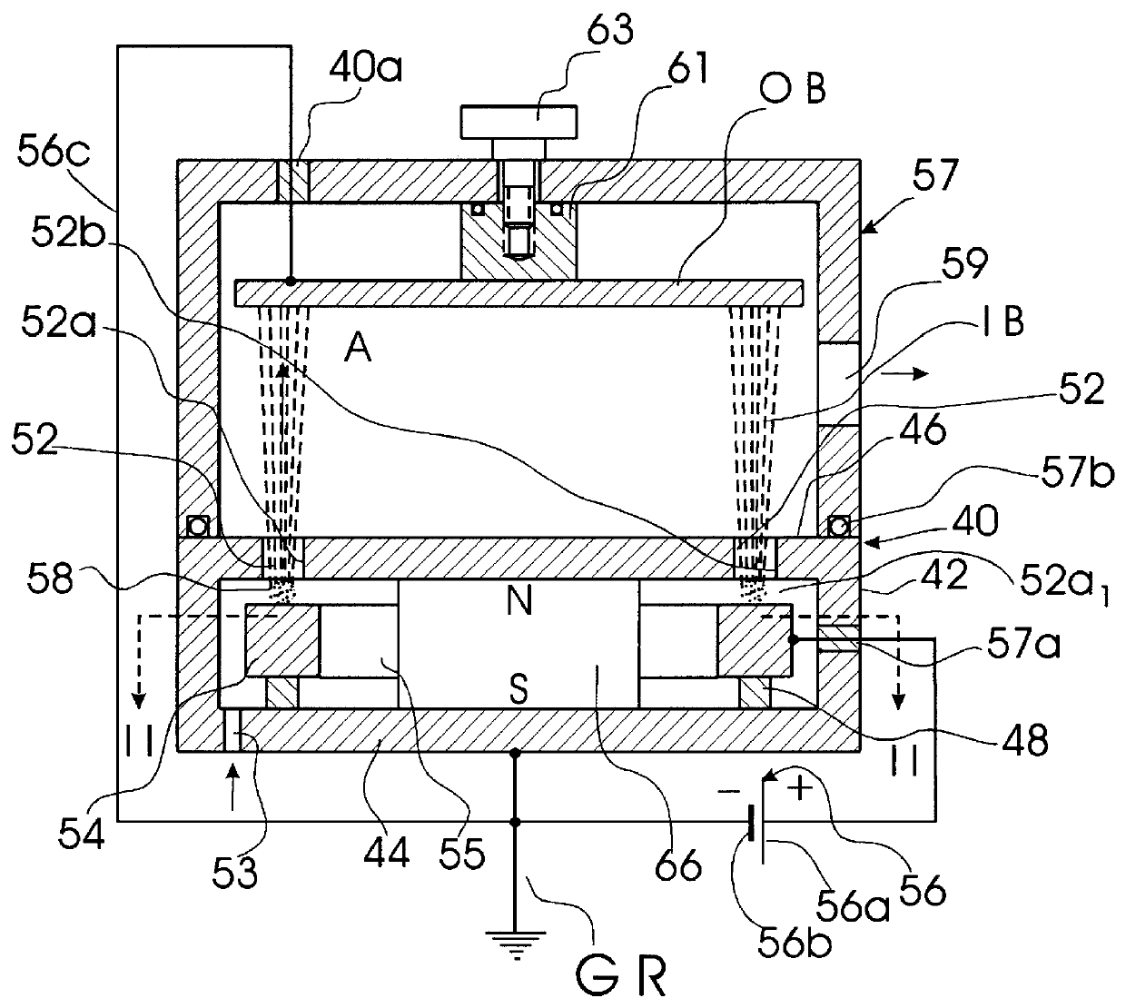
In order to better understand the principle of the invention, it would be appropriate to explain a behavior of electrons and ions in the ion-accelerating and emitting space of a cold-cathode ion source having crossed electrical and magnetic fields. Ion beam sources of the aforementioned type are characterized by the following distinguishing features: electrons are held in cross electric and magnetic fields of such a magnitude at which the Larmor radius of an electron (r.sub.e) is approximately equal to an anode-cathode distance (d), whereas the Larmor radius of an ion (r.sub.i) significantly exceeds distance "d". The definition of the Larmor radius has been given above.

In the anode-cathode space the electrons ionize the working medium, and their spatial charge compensates for the positive spatial charge of the ion beam. Since r.sub.i >>d, the magnetic field practically does not affect the ion trajectory. Ionization of practically any substance is ensured by high-energy electrons acc...


PUM

PropertyMeasurementUnit
diameteraaaaaaaaaa
widthaaaaaaaaaa
frequencyaaaaaaaaaa

Abstract

A cold-cathode ion source with a closed-loop ion-emitting slit which is provided with means for generating a cyclically-variable, e.g., alternating or pulsating electric or magnetic field in an anode-cathode space. These means may be made in the form of an alternating-voltage generator which generates alternating voltage on one of the cathode parts that form the ion-emitting slit, whereas the other slit-forming part is grounded. The alternating voltage deviates the ion beam in the slit with the same frequency of the alternating voltage. In accordance with another embodiment, the aforementioned means may be an electromagnetic coil which generates a magnetic field which passes through the ion-emitting slit, thus acting on the condition of the spatial-charge formation and, hence, on concentration of ions in the ion beam. The cold-cathode ion source may be of any type, i.e., with the ion beam emitted in the direction perpendicular to the direction of drift of electrons in the ion-emitting slit or with the direction of emission of the beam which coincides with the direction of electron drift.

Description

The present invention relates to ion-emission technique, particularly to cold-cathode ion sources used for treating internal or external surfaces of objects with a controlled position of the ion beam. More specifically, the invention relates to cold-cathode ion sources with closed-loop ion-emitting slits, in particular to a method and an apparatus for improving uniformity in ion beam density on the surfaces of treated objects and for varying the positions of ion beams with respect to the objects being treated.BACKGROUND OF THE INVENTION AND DESCRIPTION OF THE PRIOR ARTAn ion source is a device that ionizes gas molecules and then focuses, accelerates, and emits them as a narrow beam. This beam is then used for various technical and technological purposes such as cleaning, activation, polishing, thin-film coating, or etching.An example of an ion source is the so-called Kaufman ion source, also known as a Kaufman ion engine or an electron-bombardment ion source described in U.S. Pat. N...

Claims


Application Information

Patent Timeline
Patent Type & Authority Patents(United States)
IPC IPC(8): H01J27/08H01J27/02
CPCH01J27/143H01J2237/08
Inventor MAISHEV, YURIRITTER, JAMESVELIKOV, LEONIDSHKOLNIK, ALEXANDER
Owner ADVANCED ION TECH
Why Eureka
Try Eureka