

Metal powder injection moldable composition, and injection molding and sintering method using such composition
a technology of metal powder and composition, which is applied in the direction of metal-working apparatus, transportation and packaging, etc., can solve the problems of high deformation during thermal debinding, high residual carbon content of sintered body, and low efficiency
- Summary
- Abstract
- Description
- Claims
- Application Information
AI Technical Summary
Benefits of technology
Problems solved by technology
Method used
Image

Examples
example 1
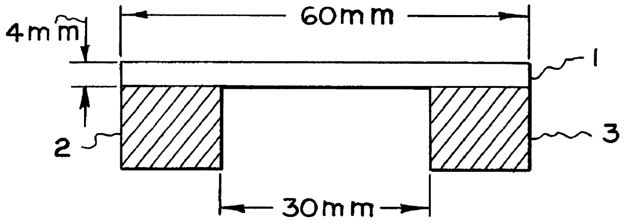
First, polyoxymethylene and polypropylene were put in a pressure kneader and melted at 160.degree. C. Thereafter, SUS316L powder (average particle size: 10 .mu.m), paraffin wax (melting point 63.degree. C.), polypropylene and polyvinyl butyral were put in the kneader and kneaded for 40 minutes. The kneaded body was taken out and pulverized to provide a moldable composition. Then, it was injection-molded at a molding temperature of 150.degree. C. to provide a molded body which was 4 mm thick, 10 mm wide and 60 mm long.
example 2
First, polyoxymethylene and polypropylene were put in a pressure kneader and melted at 160.degree. C. Thereafter, SUS304 powder (average particle size: 12 m), paraffin wax (melting point 46.degree. C.), carnauba wax and polybutyl methacrylate were put in the kneader and kneaded for 40 minutes. The kneaded body was taken out and pulverized to provide a moldable composition. Then, it was injection-molded at a molding temperature of 170.degree. C. to provide a molded body which was 4 mm thick, 10 mm wide and 60 mm long.
example 3
First, polyoxymethylene and polypropylene were put in a pressure kneader and melted at 160.degree. C. Thereafter, 8% iron-nickel powder (average particle size: 8 .mu.m), glycidyl methacrylate, paraffin wax (melting point 63.degree. C.), and urethanated wax were put in the kneader and kneaded for 40 minutes. The kneaded body was taken out and pulverized to provide a moldable composition. Then, it was injection-molded at a molding temperature of 160.degree. C. to provide a molded body which was 4 mm thick, 10 mm wide and 60 mm long.
PUM
| Property | Measurement | Unit |
|---|---|---|
| Pressure | aaaaa | aaaaa |
| Pressure | aaaaa | aaaaa |
| Angle | aaaaa | aaaaa |
Abstract
Description
Claims
Application Information