Optical diffraction grating

a technology of optical diffraction and grating, which is applied in the direction of optical waveguide light guide, waveguide type device, instruments, etc., can solve the problems of limited angular dispersion, high packaging and maintenance cost, and bulk optic components that are not suitable for more widespread use in a network

Inactive Publication Date: 2000-04-18
IPG PHOTONICS CORP
View PDF6 Cites 142 Cited by
  • Summary
  • Abstract
  • Description
  • Claims
  • Application Information

AI Technical Summary

Problems solved by technology

The use of bulk-optic components tends however to result in high packaging and maintenance costs.
Accordingly, while the use of such components might be feasible if wavelength multiplexing/demultiplexing was to be confined to a few core switc

Method used


Image

  • Optical diffraction grating
  • Optical diffraction grating
  • Optical diffraction grating

Examples


Embodiment Construction

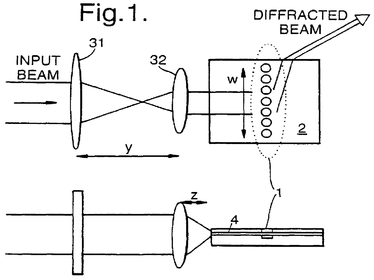
A grating comprises a region of photonic crystalline material 1 formed in a multi-layered planar substrate 2. An optical system comprising a first lens 31 with a focal length of, e.g. 10 cm, and a second lens 32 with a focal length of, e.g. 1 cm collimates an input optical beam. The lenses 31,32 are separated by a distance y which is equal to the sum of the focal lengths. The lens 32 is spaced from a facet of the planar substrate 2 by a distance z of 1 cm in this example. The optical system couples light into a waveguide layer 4 where it propagates to meet the photonic crystal 1 with normal incidence. A grazingly emergent diffracted beam is transmitted through the photonic crystal 1 and propagated through the waveguide layer 4 and emerges from a side facet of the planar substrate. The emergent beam tends to diverge in the direction normal to the planar substrate. Optionally a cylindrical lens may be used to collimate the emergent beam.

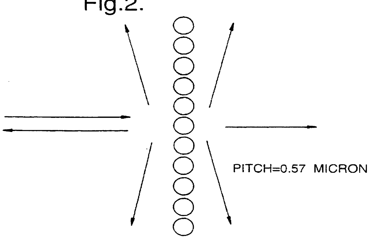
FIG. 2 shows schematically the configuration of ...


PUM


Abstract

PCT No. PCT/GB97/00817 Sec. 371 Date Apr. 13, 1998 Sec. 102(e) Date Apr. 13, 1998 PCT Filed Mar. 24, 1997 PCT Pub. No. WO97/36198 PCT Pub. Date Oct. 2, 1997An optical diffraction grating is formed from a region of photonic crystalline material Light is coupled into the photonic crystalline material, and the grazingly emergent output beam is collected. The photonic crystalline material may include an array of holes formed in a substrate of dielectric material, e.g., InP, and integrated with planar waveguide structures.

Description

1. Field of the InventionThe present invention relates to an optical diffraction grating suitable for use, for example, as a wavelength multiplexer / demultiplexer in an optical telecommunications system.2. Related ArtBulk optic diffraction gratings are well known, and it has previously been proposed to use such gratings as passive multiplexers / demultiplexers in optical networks employing wavelength division multiplexing (WDM). The use of bulk-optic components tends however to result in high packaging and maintenance costs. Accordingly, while the use of such components might be feasible if wavelength multiplexing / demultiplexing was to be confined to a few core switches, bulk optic components are not suitable for more widespread use in a network. Current interest in WDM centres on its use in local access networks in combination with optical time division multiplexing (OTDM) for longer links in the network. There remains a need therefore for a grating which is sufficiently robust and in...

Claims


Application Information

Patent Timeline
IPC IPC(8): G02B6/124G02B6/122G02B5/18G02B6/12G02B6/293H01P1/00H01P3/20
CPCG02B6/124
Inventor BURT, MICHAEL GGRANT, ROBERT S
Owner IPG PHOTONICS CORP
Why Eureka
Try Eureka