Signal detector and method for detecting signals having selected frequency characteristics

a signal detector and frequency characteristic technology, applied in the direction of instruments, measurement devices, electrical appliances, etc., can solve the problems of high noise susceptibility of the detection device, unreliable readout, and low signal-to-noise ratio of the detection device versus the background noise, so as to reduce the susceptibility to mechanical vibration and temperature change, and the effect of low production cos

Inactive Publication Date: 2000-05-02
RADIAULICS
View PDF14 Cites 52 Cited by
  • Summary
  • Abstract
  • Description
  • Claims
  • Application Information

AI Technical Summary

Benefits of technology

Another object of the present invention is to provide a new and useful signal detector which is relatively inexpensive to produce and which is lightweight, compact, and portable.
A further object of the present invention is

Problems solved by technology

For signal detectors specifically constructed to monitor a broad range of oscillatory signals, certain problems arise where those circuits seek to monitor signals having certain frequency characteristics.
For example, many signal detectors exhibit a high susceptibility to noise and produce unreliable readouts where random noise signals fall within the target frequency range.
Also, these systems often encounter problems with signal-to-noise ratio for the target signals versus the background noise.
While being relatively inexpensive, crystal based systems have exhibited limited performance and have significant sensitivity problems where the ambient environment is quiet.
These crystal based systems are also susceptible to noise and have problems with signal-to-noise ratio.
In addition, crystal based systems are susceptible to mechanical vibrations and temperature changes which can affect their sensitivity and yield false readings.
Further, crystal based systems often and undesirably respond to infra-sonic and sonic signals that modulate the system so that again faulty readings occur.

Method used


Image

  • Signal detector and method for detecting signals having selected frequency characteristics
  • Signal detector and method for detecting signals having selected frequency characteristics
  • Signal detector and method for detecting signals having selected frequency characteristics

Examples


Embodiment Construction

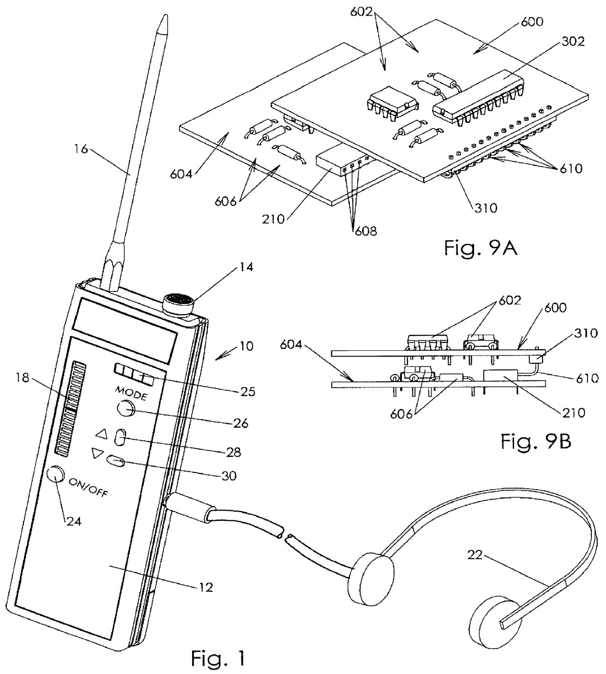
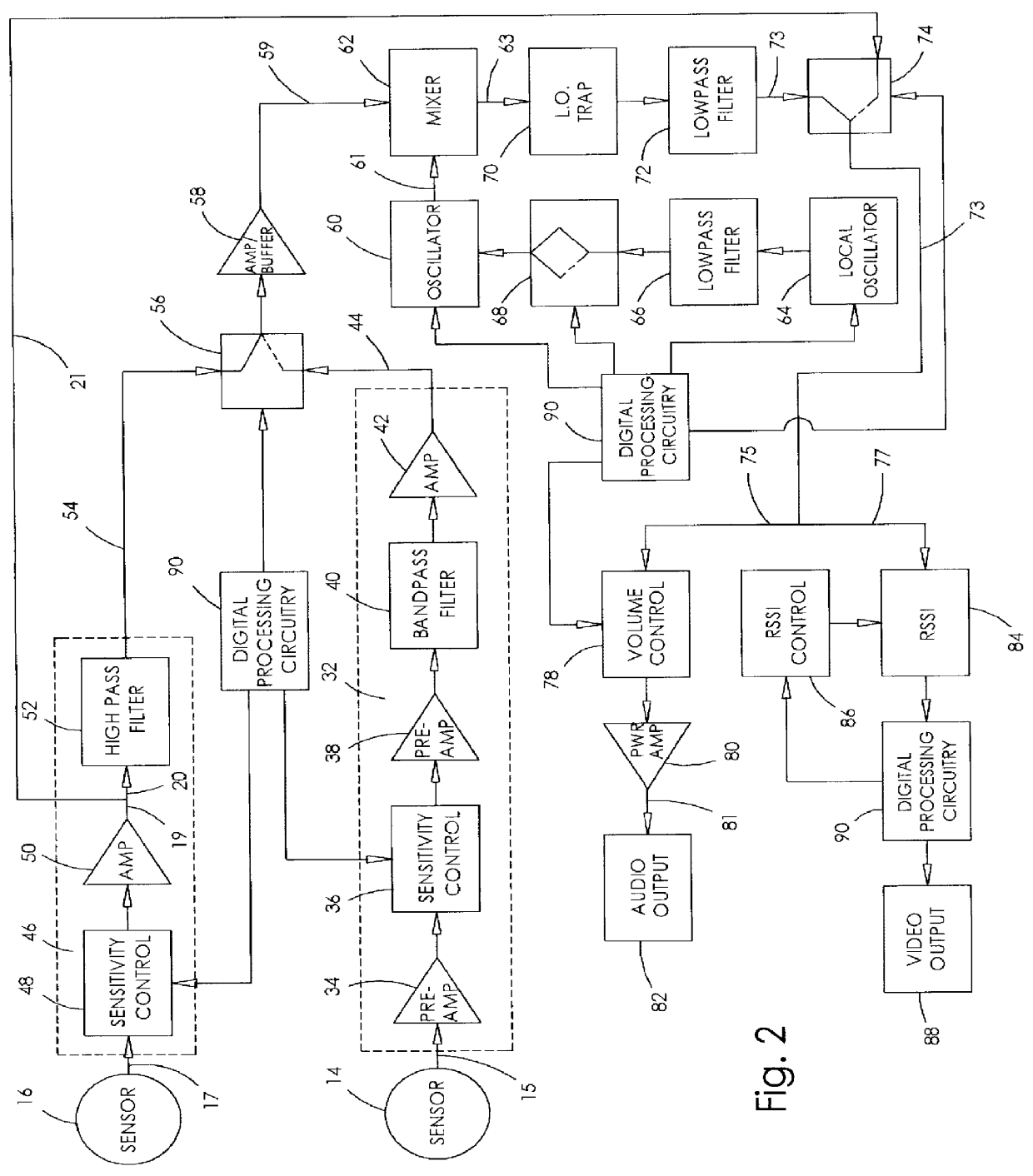
The present invention is directed to detectors for sound signals, especially those adapted to respond over a selected range to convert ultrasonic and sonic signals into a display which may be either audible of visual. More particularly, this invention is directed to a very versatile, yet compact and portable unit which is relatively inexpensive to produce. This signal detector produces a relatively clean audio output of the type typically familiar to users of detectors with a minimum number of components. Moreover, this signal detector produces visual output of peak received signal strength which is more representative of the received signal as opposed to an average of such signal strength. As will be appreciated from the description to follow, the signal detector of the present invention is much more versatile than my previous versions due to its dual sensor construction and digital processing circuitry.

It should be understood that the signal detector and method according to the pr...


PUM


Abstract

The present invention generally relates to procedures and apparatus for monitoring incoming signals to detect the presence of selected target signals contained within the universe of signals received. More particularly, the present invention is directed to monitoring audio signals to detect selected ultrasonic and sonic signals in an ambient environment. Thus, the present invention is even more specifically directed to leak detectors and bearing wear indicators and methods for detecting sound signals which either travel in the air or are present in solids.

Description

A variety of different signal detectors have been developed in the past with many of these including electronic circuits incorporating tuning circuitry adapted to receive, filter and process signals within a selected frequency range. For signal detectors specifically constructed to monitor a broad range of oscillatory signals, certain problems arise where those circuits seek to monitor signals having certain frequency characteristics. For example, many signal detectors exhibit a high susceptibility to noise and produce unreliable readouts where random noise signals fall within the target frequency range. Also, these systems often encounter problems with signal-to-noise ratio for the target signals versus the background noise. In order to solve these problems, many existing signal detectors resort to superheterodyning in order to increase sensitivity, eliminate noise and shift frequency bands. As noted above, the present invention especially concerns itself with the detection of ultr...

Claims


Application Information

Patent Timeline
IPC IPC(8): G01H3/00G01H1/00
CPCG01H3/00G01H1/00
Inventor KOMNINOS, NIKOLAOS I.
Owner RADIAULICS
Why Eureka
Try Eureka