Multi-assay plate cover for elimination of meniscus

a technology for meniscus and plate covers, applied in chemical methods analysis, laboratory glassware, instruments, etc., can solve the problems of affecting the concentration of reactants, photometric analysis, and inability to completely correct the effect of meniscus

Inactive Publication Date: 2000-06-13
MOLECULAR DEVICES
View PDF6 Cites 120 Cited by
  • Summary
  • Abstract
  • Description
  • Claims
  • Application Information

AI Technical Summary

Benefits of technology

A unique cover has now been discovered that eliminates the problems associated with the meniscus effect and the evaporation effect. In fact, the unique cover of the present invention eliminates both the meniscus and evaporation altogether.

Problems solved by technology

Thus, it is not possible to completely correct for meniscus effect on the light transmission at a first wavelength by measuring the effect at a second wavelength.
Evaporation is another effect that causes several problems in photometric analysis.
First, evaporation affects the concentration of the reactants as the volume of the liquid sample in the wells decreases.
Second, due to the heat of evaporation, evaporation affects the steady-state temperature of the samples.
Third, different evaporation rates of a liquid sample within different wells of the MAP will cause the temperature of such liquid sample to vary from well-to-well.
All of these three effects from evaporation result in inaccurate photometric analysis.
Evaporation is a particularly acute problem in the analysis of small volume samples (e.g. 200 .mu.l or less) in MAP wells, because of the large surface to volume ratio.
Further, evaporation tends to be a serious problem for liquid samples having an appreciable vapor pressure at ambient temperature.
Furthermore, the amount of condensation frequently is not identical from well to well, thereby causing variability and error in optical density measurements.
In addition, prior covers did not address the problems encountered by the meniscus effect.
The application of an antifogging agent to a MAPs cover is an improvement over an untreated cover, however it has problems of its own.
First, the antifogging film is translucent and scatters light rather than being completely transparent.
Second, the translucent cover becomes increasingly translucent as the air above the wells becomes saturated with aqueous vapor.
Thus, prior to the present invention, existing covers for MAPs, even in combination with an antifogging agent, failed to eliminate the problems of evaporation and condensation in MAPs, and moreover, did not address, let alone eliminate, the problems due to the meniscus effect.
A major problem with such MAP covers is that they are not usable to read the optical density of samples contained at sample sites in MAPS.
These projections, therefore, are unable to transmit light to a substantial fraction of the cross-sectional area the wells of the 96-well MAPs.
Also, the narrowest internal diameter of the projections is insufficient to accommodate customary light beams wider than about 1.0 mm in diameter (allowing for .+-.0.5 mm of optical misalignment of the light beam with respect to the long axis of the projections).
With such prior art covers, light passing down the long axis of the projections strikes the internal side edges of the projections thereby causing an error in the measurement of the relative amount of light transmitted through sample sites in the MAP.
Also, the projections of such prior art covers are excessively long to be used with the MAPs with which they are compatible, such that the optical pathlength, through the samples in a MAP, would be less than 2.0 mm and in some cases less than 1.0 mm.
Also, the distal bottom ends of the projections are extremely rough such that any light beam traveling through the projections would be scattered greatly so as to miss the photodetector placed below the MAP wells, thus causing error in determination of sample concentration.

Method used


Image

  • Multi-assay plate cover for elimination of meniscus
  • Multi-assay plate cover for elimination of meniscus
  • Multi-assay plate cover for elimination of meniscus

Examples


example 2

Simultaneous monitoring of the extracellular acidification of TF-1 cells in a microplate reader that normally causes aqueous samples to fog MAP covers at elevated temperatures is now possible when the cover of the present invention is used in place of a standard Nunclon.RTM. Delta MAP cover. A flat bottom Nunclon.RTM. Delta multi-assay plate identical to that used in Example 1 (96 assay sites arranged in twelve columns, numbered 1 through 12 and eight rows, identified as letters A through H) was used in the present example. A volume of 125 .mu.l of running media was placed in assay sites in column Nos. 5 and 6. Running media was composed of balanced salts solution (BSS), 1 mg / ml human serum albumin, 0.7 mM HEPES and 20 mg / L phenol red. The BSS contained 0.6 mM MgCl.sub.2 --6H.sub.2 O, 3.0 mM KCl, 1.0 mM KH.sub.2 PO.sub.4 anhyd., 10 mM D-glucose, 0.3 mM CaCl.sub.2 --2H.sub.2 O, and 130 mM NaCl.

Next, a total of about 200,000 TF-1 cells in 75 .mu.l of ice cold running media were pipett...

example 3

FIG. 10 shows the results of the above experiment repeated, but employing a standard MAP cover instead of the cover of the present invention. In contrast to the previous case where the cover of the present invention was used, changes in OD.sub.560 were erratic, nonmonotonic and spanned a relatively large range. The individual plots (OD.sub.560 versus time) in FIG. 10 are "windowed" over a significantly larger range totaling 0.6 optical density units, whereas the results obtained with the cover of the present invention (FIG. 9) are windowed over a smaller range totaling 0.15 optical density units. When the standard MAP cover was used, the replicate OD.sub.560 measurements were not-reproducible for either the assay sites having TF-1 cells or for the control assay sites. The non-reproducibility is attributed to light scattering caused by water droplets (i.e., fog) which forms on the standard MAP cover. The water droplets scatter light of interrogating light beams within the absorbance ...

example 4

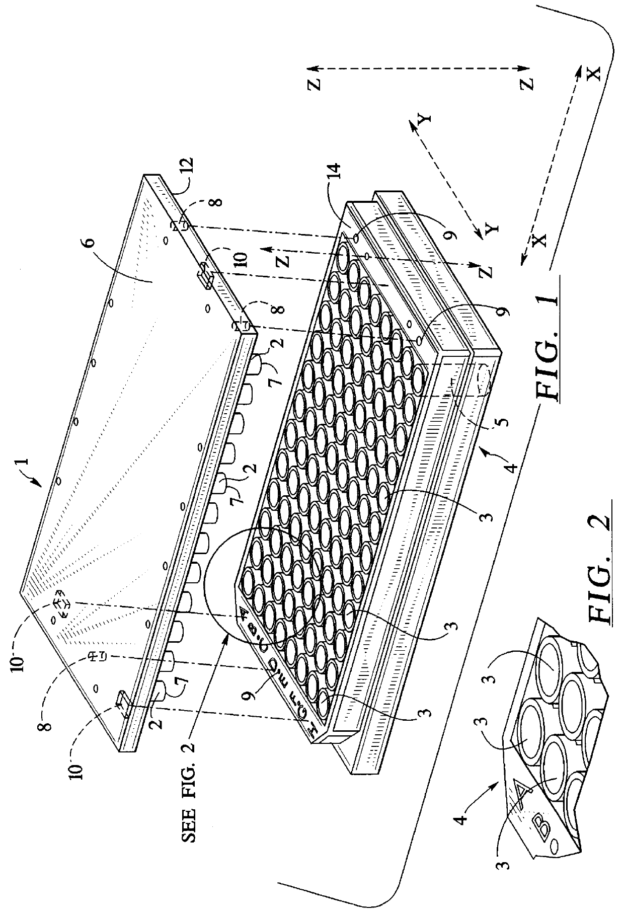
First 200 microliters of pure water was placed, with a pipette, into all ninety-six (96) sample site wells of a Nunc No. 269620 flat-bottom MicroWell.TM. MAP. Such MAPs are available from Fisher Scientific as Cat. No. 12-565-226. Secondly, MAP cover 1 was placed on the MAP 4. Care was taken not to trap any bubbles below the projections 2 of the cover 1. The optical path through the water, as measured with a mechanical calipers, was 3.3 mm. Thirdly, the MAP with attached cover, was placed in a Thermomax.TM. microplate absorbance reader at room temperature (about 23.degree. C.) and the optical densities of the sample sites were measured at 650 nanometers. The measured optical densities of the ninety-six sample sites containing pure water ranged from 0.076 to 0.167 optical density units. Thus, the optical density at 650 nanometers was less than 0.170 in all of the sample sites, with a range of 0.091 optical density units between all ninety-six sample sites. Repeated measurements were h...


PUM

PropertyMeasurementUnit
volumeaaaaaaaaaa
internal diameteraaaaaaaaaa

Abstract

A constant pathlength multi-assay plate cover for multi-assay plates, comprising, a flat top side and a flat bottom side, the bottom side having solid cylindrical projections of equal length extending downwardly from the flat bottom side, wherein each cylindrical projection is centered about the optical axis passing through a corresponding sample well of a multi-assay plate, thereby eliminating the meniscus and evaporation effects.

Description

Spectrophotometers are used to measure the optical density of liquid samples placed in a cuvette, i.e., a liquid sample container having at least two parallel transparent walls. In a spectrophotometer measurement, a horizontal light beam from a light source passes through air and then into one of the parallel walls of the cuvette, then through the sample, then through the opposite parallel wall of the cuvette, and then through air where it is then detected by a light detector.In contrast to horizontal light beam spectrophotometers, microplate readers are designed as vertical light beam photometers. In a microplate reader, a vertical beam of light is used to read the optical density of samples contained in the wells of multi-assay plates (MAPs) because the wells are arranged in rectangular arrays (e.g. 8.times.12). In such rectangular arrays, neighboring wells would be in the way of a horizontal light beam. In microplate readers, a vertical beam of light from a light source passes th...

Claims


Application Information

Patent Timeline
Patent Type & Authority Patents(United States)
IPC IPC(8): B01L3/00
CPCB01L3/50853
Inventor HAFEMAN, DEAN G.CRAWFORD, KIMBERLY L.GALLAGHER, STEVEN J.
Owner MOLECULAR DEVICES
Why Eureka
Try Eureka