Electrolytic capacitor and method for producing the same

a technology of electrolytic capacitors and capacitors, which is applied in the manufacture of electrolytic capacitors, non-metal conductors, conductors, etc., can solve the problems of reaction not being completely stopped, increasing the consumption of raw materials, and affecting the effect of reaction

Inactive Publication Date: 2000-07-11
PANASONIC CORP
View PDF11 Cites 22 Cited by
  • Summary
  • Abstract
  • Description
  • Claims
  • Application Information

AI Technical Summary

Problems solved by technology

Therefore, the one-solution method is disadvantageous in the formation of a conductive polymer in the depth of the pores of the porous body.
However, in the one-solution method, the reaction cannot be stopped completely even if the monomer solution and the oxidizing solution are mixed in a low temperature.
This results in an increase in the consumption of raw materials.
However, in the two-solution method, the solution in which the porous body is first dipped diffuses into the solution in which the porous body is secondly dipped, and thus a reaction occurs.
This reaction occurring outside the porous body causes the yield of the conductive polymer adhering to the porous body to be low.
In addition, the yield of the conductive polymer is not high.
However, the above step cannot to applied to a monomer that is volatilized readily.
The two-solution method also poses the problem that a conductive polymer is hardly formed on an oxide film in the deeper portion of a porous body.
This rapid reaction makes it difficult to form a conducti

Method used


Image

  • Electrolytic capacitor and method for producing the same
  • Electrolytic capacitor and method for producing the same
  • Electrolytic capacitor and method for producing the same

Examples


Embodiment Construction

Hereinafter, the present invention will be described by way of examples, but the present invention is not limited thereto.

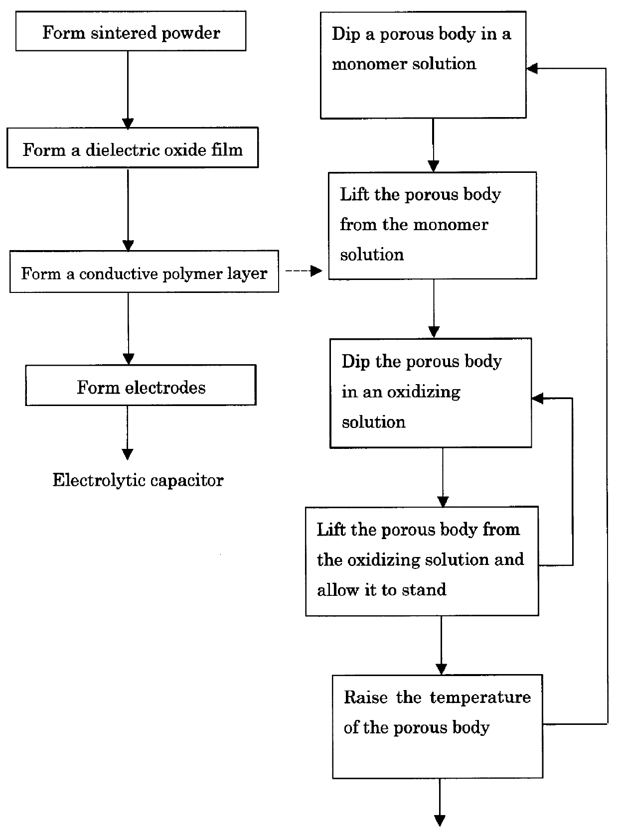
Preparation of a monomer solution: Pyrrole was dissolved in an aqueous solution containing 10 vol % of isopropyl alcohol so that the concentration of pyrrole was 1.0M (mol.multidot.dm.sup.-3). Thus, a monomer solution is prepared.

Preparation of an oxidizing solution: Iron sulfate (III) as an oxidant and alkyl naphthalene sulfonate ion in the form of a Na salt as a dopant were dissolved in an aqueous solution containing 10 vol % of isopropyl alcohol so that the concentration of iron sulfate (III) was 0.25M, and the concentration of alkyl naphthalene sulfonate ion was 0.03M. Thus, an oxidizing solution is prepared.

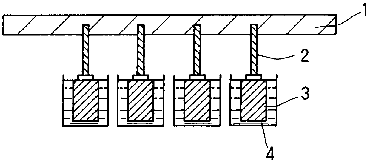
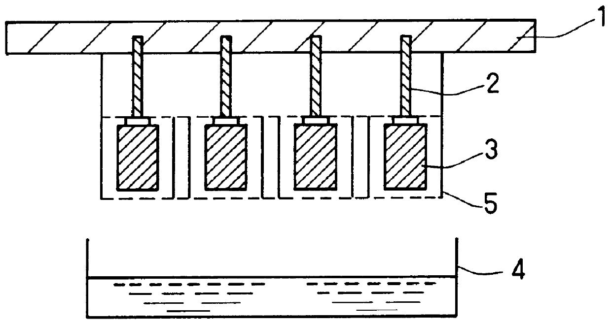
Formation of a porous body for a capacitor: Tantalum powders together with a lead were subjected to compression molding, and then sintered so as to form a porous body of 1.4 mm.times.3.0 mm.times.3.8 mm. Furthermore, the entire surface of this tantalum po...


PUM

PropertyMeasurementUnit
Fractionaaaaaaaaaa
Angleaaaaaaaaaa
Temperatureaaaaaaaaaa

Abstract

The present invention provides a method for producing an electrolytic capacitor including a porous body of a valve metal, an oxide film on a surface of the valve metal, and a conductive polymer layer on a surface of the oxide film. The step of forming the conductive polymer layer on the surface of the oxide film includes the steps of dipping the porous body in a monomer solution; lifting the porous body from the monomer solution and dipping the porous body in an oxidizing solution; and lifting the porous body from the oxidizing solution and allowing the porous body to stand. In the step of dipping the porous body in the oxidizing solution, a period for which the porous body is dipped in the oxidizing solution is equal to or shorter than a period in which 30% of the monomer contained in pores of the porous body diffuses and flows into the oxidizing solution. Alternatively, the volume of the oxidizing solution can be less than three times that of the porous body. The above method can be performed by replacing the monomer solution and the oxidizing solution with each other. Furthermore, a temperature of the porous body is maintained at a low temperature (e.g., 10 DEG C. or less) in the step of dipping the porous body in the oxidizing solution.

Description

1. Field of the InventionThe present invention relates to a method for producing an electrolytic capacitor including an electrode (anode) formed of a porous body of a valve metal such as aluminum and tantalum. In particular, the present invention relates to a method for producing an electrolytic capacitor including a conductive polymer layer as the other electrode (cathode) corresponding to the electrode (anode) formed of the valve metal.2. Description of the Prior ArtConventionally, a one-solution method is known as a method for forming a conductive polymer layer for an electrolytic capacitor. In the one-solution method, a mixture of a monomer solution and an oxidizing solution is introduced on an oxide film formed on a surface of a porous body of a valve metal. However, in the one-solution method, immediately after the monomer and the oxidant are mixed, a reaction therebetween (oxidation polymerization) is initiated. Therefore, the activity of the mixed solution is reduced before ...

Claims


Application Information

Patent Timeline
IPC IPC(8): H01G9/02H01G9/00H01G9/025
CPCH01G9/0036H01G9/025Y10T29/417
Inventor HAMADA, TAKAHIROIGAKI, EMIKOTANAHASHI, MASAKAZUHAYASHI, CHIHARUTSUJI, YASUNOBU
Owner PANASONIC CORP
Why Eureka
Try Eureka