Low emission power plant and method of making same

a power plant and low-emission technology, applied in the field of mechanical power pants, can solve the problems of increased oxidation rate of soluble organic fractions, increased exhaust temperature, and substantial problems in the control of emissions of such engines

Inactive Publication Date: 2000-08-15
CLEAN CAM TECH SYST
View PDF9 Cites 34 Cited by
  • Summary
  • Abstract
  • Description
  • Claims
  • Application Information

AI Technical Summary

Benefits of technology

Another object of the invention is to provide a mechanical power plant of the aforementioned character which includes a specially modified, conventional two-stroke uniflow-scavenged diesel engine that has a lower than normal exhaust valve lift and a shorter than normal exhaust valve open time, thereby effectively increasing the amount of residual exhaust gases remaining in the combustion chamber following the scavenge stroke.
Another object of the invention is to provide a mechanical power plant as described in the preceding paragraphs which provides for a greater than normal flow of oxygen-rich air into the combustion chamber of the modified diesel engine so as to accomplish more complete and efficient combustion of fuel and, at the same time, accelerate the oxidation of the soluble organic fraction, that is the unburned lubricating oil and fuel fraction formed in the exhaust system and trapped on the particulate emission sampling filter.
Another object of the invention is to provide a unique mechanical power plant in which the nitrogen oxide emissions exhausted from the diesel engine component are effectively maintained at levels below those set by the air quality regulatory agencies.

Problems solved by technology

While diesel engines are durable, reliable, and economical, the control of emissions from such engines has presented substantial problems.
This phenomenon leads to more thorough combustion of the fuel and also generally leads to higher exhaust temperatures.
Higher exhaust temperatures, in turn, lead to a greater oxidation rate of the soluble organic fraction thus further lowering the level of undesirable particulate matter emission from the engine.

Method used


Image

  • Low emission power plant and method of making same
  • Low emission power plant and method of making same
  • Low emission power plant and method of making same

Examples


Embodiment Construction

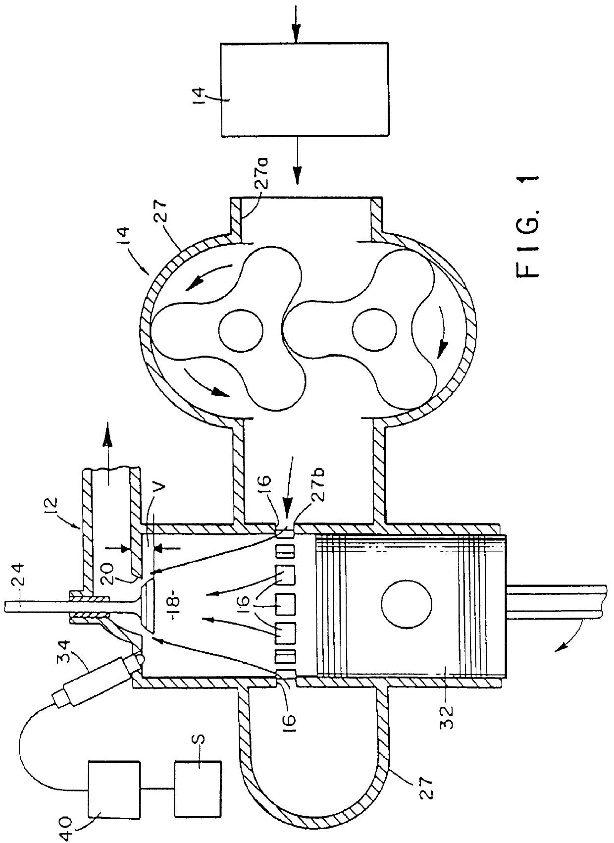
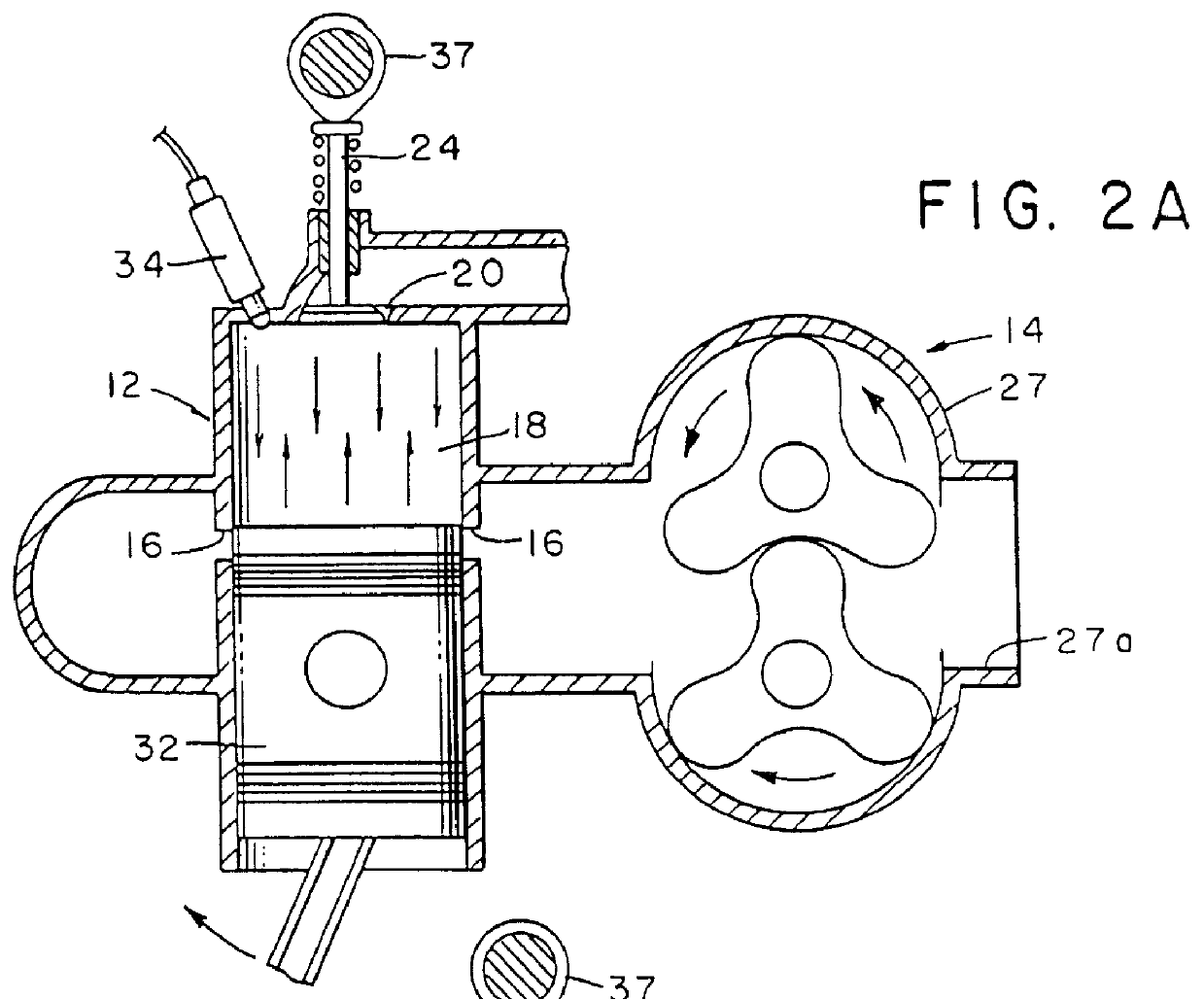
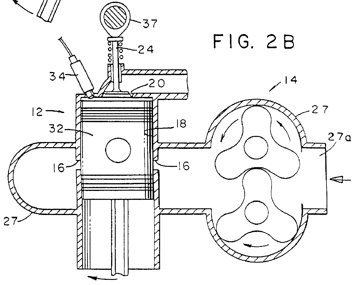
Referring to the drawings and particularly to FIGS. 1, 2A, 2B, and 2C, a mechanical power plant of the general character of the apparatus of the present invention is diagrammatically illustrated. These figures are general in character and do not show all of the various standard components of the power plant, which components are well known to those skilled in the art. As previously mentioned, one form of the power plant of the invention comprises a modification of a commercially available power plant which is also of a character well known to those skilled in the art and includes a turbocharger component and a diesel engine component. In a manner presently to be described, the turbocharger component along with a blower unit functions to controllably deliver air under pressure to the inlet ports of the combustion chamber of the diesel engine component. The diesel engine component of the conventional power plant has a combustion cycle and a scavenge stroke and includes one or more val...


PUM


Abstract

A low emission power generating apparatus which comprises a modified two-stroke diesel engine component and a modified turbocharger component which has a relatively low aspect ratio. The diesel engine component is a modification of a conventional two-stroke diesel engine design and includes an exhaust valve cam of unique design that has a cam profile which results in a later than-normal exhaust valve opening and an earlier-than-normal valve closing so that the time during which the exhaust valve remains open is shorter than normal, thereby causing a substantially greater volume of residual gases to remain in the combustion chamber following the scavenge stroke. This increase in the volume of the residual exhaust gases within the chamber leads to an increase in compression temperature and effectively increases the compression ratio and consequently the compression pressure. Because of the heat absorption capacity of these residual exhaust gases, the exhaust gases remaining in the chamber following the scavenge stroke tend to absorb combustion heat and thereby effectively reduce the peak combustion temperature. This reduction in peak combustion temperature advantageously results in the lower than normal formation of nitrogen oxide (NOx) and, therefore, allows advancement of the injection timing, while still maintaining the NOx emissions coming from the engine lower than those legislatively mandated. Advantageously, the advance in injection timing, which increases NOx emissions, by definition has the effect of also reducing particulate matter emissions. Thus, by increasing the volume of residual exhaust gases within the cylinder, substantial particulate matter emission reductions can be achieved, while at the same time maintaining NOx emissions well below mandated limits. The modified turbocharger component provides an additional charge of oxygen-rich air into the combustion chamber which effectively increases the compression pressure, which, in turn, leads to an earlier start of combustion because of the combustible mixture reaching its auto-ignition temperature at an earlier point in the cycle. This phenomenon leads to more thorough combustion of the fuel and also generally leads to higher exhaust temperatures. Higher exhaust temperatures, in turn, lead to a greater oxidation rate of the soluble organic fraction thus lowering the level of emission from the engine of undesirable particulate matter.

Description

1. Field of the InventionThe present invention relates generally to mechanical power pants. More particularly, the invention concerns a low emission power plant which comprises a modified diesel engine component and a modified turbocharger component which has a relatively low turbocharger aspect ratio. The diesel engine component is a modification of a two-stroke, uniflow-scavenge diesel engine design and includes an exhaust valve cam of unique design that has a cam profile which results in a later-than-normal exhaust valve opening and an earlier-than-normal valve closing so that the time during which the exhaust valve remains open is shorter than normal thereby causing a substantially greater volume of residual gases to remain in the combustion chamber following the scavenge stroke.2. Discussion of the Prior ArtMechanical power plants embodying diesel engines are widely used in both on-road and off-road applications. Such power plants have always been popular for use in large truck...

Claims


Application Information

Patent Timeline
Patent Type & Authority Patents(United States)
IPC IPC(8): F02B25/00F02B23/02F02B25/04F02B33/36F02B23/06F02B33/00F02B3/06F02B75/02F02B3/00F02M25/07
CPCF02B23/0672F02B23/0696F02B25/04F02B33/36F02M25/0752F02B3/06F02B23/0621F02B23/0624F02B23/0651F02B2075/025F02B2275/14F02M25/0706Y02T10/121Y02T10/125Y02T10/123F02M26/04F02M26/01Y02T10/12
Inventor GREEN, EDWARD
Owner CLEAN CAM TECH SYST
Why Eureka
Try Eureka