

Method for wide range gas flow system with real time flow measurement and correction
a gas flow system and real-time flow technology, applied in process and machine control, non-electric variable control, instruments, etc., can solve the problems of voltage imbalance, unfavorable use of purely volumetric flow control devices, and the fact that known mass flow controllers can also be one of the least reliable parts of such a system
Inactive Publication Date: 2000-09-19
CYBER INSTR TECH LLC AN ARIZONA LIMITED LIABILITY +1
View PDF22 Cites 515 Cited by
- Summary
- Abstract
- Description
- Claims
- Application Information
AI Technical Summary
Benefits of technology
The invention affords its users with a number of distinct advantages. Chiefly, the invention ensures accurate process gas delivery by taking separate mass flow measurements during gas delivery, and comparing the measurements to more accurately measure (and optionally regulate) gas flow. Mass flow with the present invention is more accurate because the invention repeatedly measures gas flow and corrects these measurements, during "real time" actual gas delivery. The invention may be implemented in one embodiment to more accurately measure gas flow rate using floating reference differential pressure transducers. In contrast to the prior art, these floating reference pressure transducers provide a greater range of measurement and higher resolution. As another advantage, the floating reference pressure transducers may be used with corrosive process gasses, since transducers' delicate back sides are isolated through coupling to a reference conduit containing a safe gas at a carefully controlled pressure.
The invention is also beneficial in its broad application. In addition to applications in semiconductor manufacturing, the invention may also be used to accurately deliver gas for coating windows, metals, and other materials. The invention also provides a number of other advantages and benefits, which should be apparent from the following description of the invention.
Problems solved by technology
Since the relationship between mass and volume is not constant, and depends on other factors, purely volumetric flow control devices are not particularly useful.
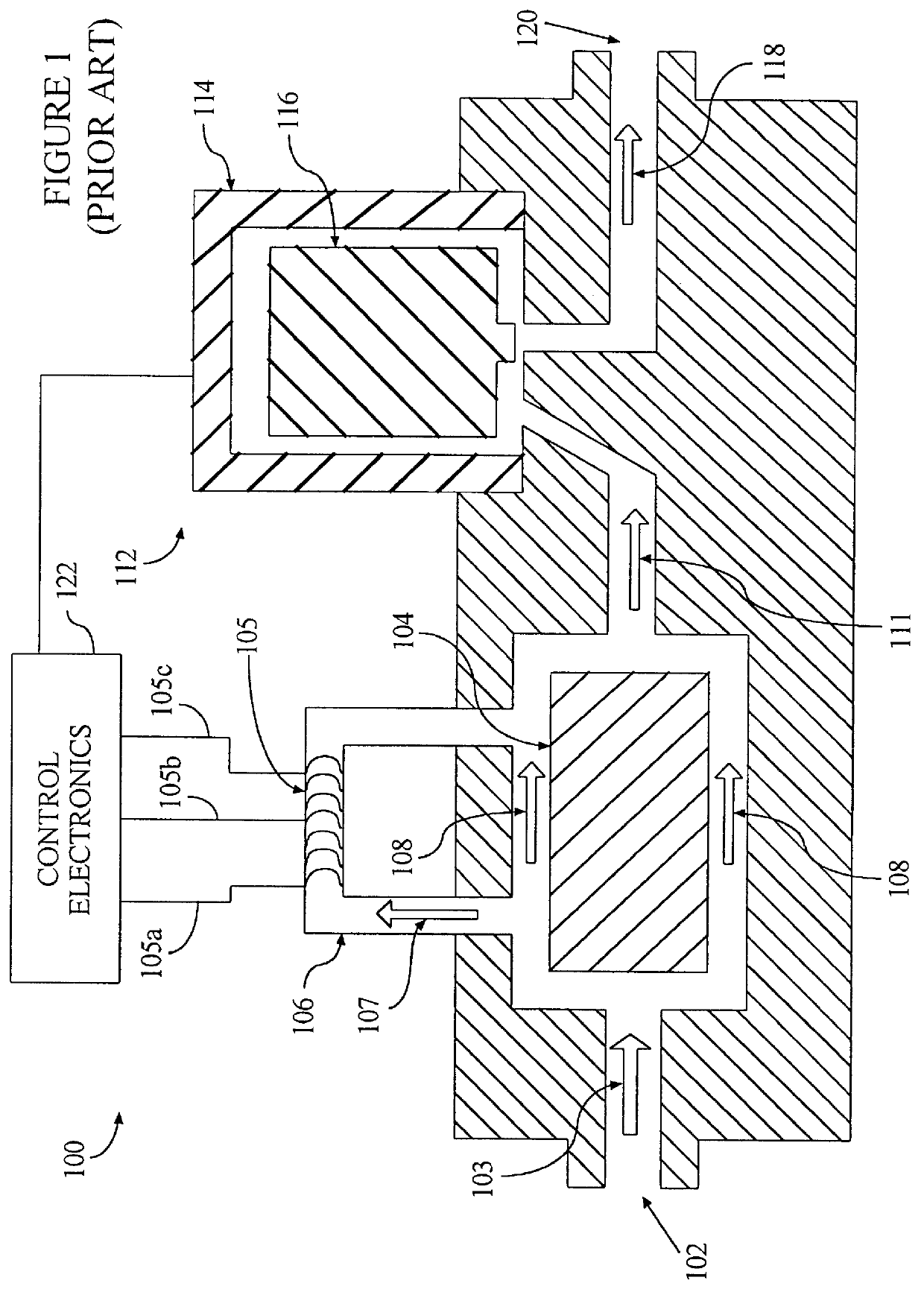
The amount of mass flow determines the amount of thermal transfer, which results in a directly proportional voltage imbalance between the winding 105a-105b and the winding 105b-105c.
Unfortunately, known mass flow controllers can also one of the least reliable parts of such a system.
Nonetheless, several different factors cause undesirable variations in mass flow calibration and performance.
Condensation forming in the bypass flow path or elsewhere in the flow path is another source of calibration error.
Aging of the windings and the nature of the thermal contact between the windings and the outside of the tube cause long term calibration drift.
Changes in chemical composition of the process gas as it is subjected to the winding heat can also affect the integrity of the process.
Although the Kennedy system may be useful for its intended purpose, it may prove inadequate for applications seeking to precisely control the mass flow rate.
Also, small incremental variations in mass flow rate can occur undetected in the Kennedy system because, as recognized by the present inventors, Kennedy lacks any continuous or real-time measurement and flow control means.
Thus, the Kennedy approach may not be satisfactory for applications that seek to precisely control mass flow.
In the semiconductor manufacturing line, misdelivery of process gasses can be extremely costly.
In some cases, if the process gas is incorrectly delivered to a silicon wafer in the process chamber, the wafer may be ruined.
And, since economy warrants growing larger and larger silicon ingots, these large silicon wafers are more costly to scrap if damaged.
Furthermore, in the event of such an error, its is expensive to repair or replace the mass flow controller and repeat the manufacturing run.
In many cases, manufacturing downtime can result in lost revenues exceeding $125,000 per hour.
In view of these limitations, known mass flow controllers are not completely adequate for some applications due to certain unsolved problems.
In this endeavor, the inventors have considered the otherwise unrecognized limitation that Wilmer's approach, which corrects the setpoint and not the flow measurement itself, does not enable secondary monitoring devices or systems to receive an actual flow signal or value.
As another limitation, Wilmer's method of flow control requires that gas flow at sonic velocities through an orifice, thus eliminating the possibility of application for the delivery of process materials that suffer adverse effects from this exposure due to such factors as solution alteration, chemical dissociation, or other undesirable effects to the characteristics of the material.
As another limitation of the Wilmer's approach, gas flow controller calibration is performed infrequently, since Wilmer's gas flow controller calibration can only performed off-line, after the process run.
For those applications that would benefit from more frequent calibration, Wilmer's approach may be inadequate.
Furthermore, Wilmer's approach is wholly inadequate for single run gas delivery processes, where any post-delivery calibration is moot.
Such converters are, however, unnecessary if the valves and sensing devices in the system 200 have digital inputs / outputs.
Method used
View moreImage
Smart ImageViewing Examples

Examples
Embodiment Construction
While the foregoing disclosure shows a number of illustrative embodiments of the invention, it will be apparent to those skilled in the art that various changes and modifications can be made herein without departing from the scope of the invention as defined by the appended claims. Furthermore, although elements of the invention may be described or claimed in the singular, the plural is contemplated unless limitation to the singular is explicitly stated.
Login to View More PUM
 Abstract
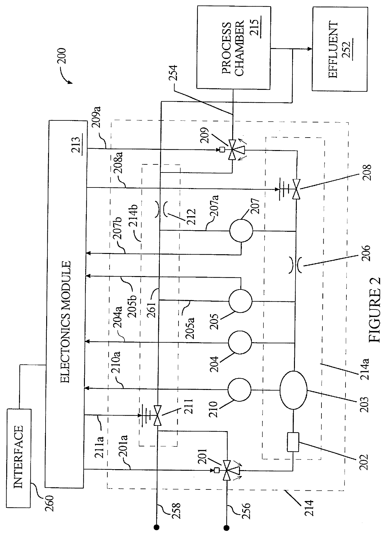
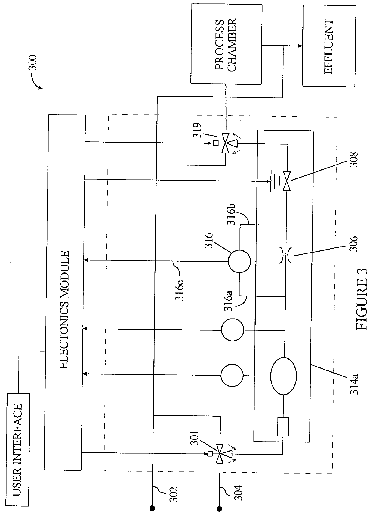
A gas delivery system accurately measures and optionally regulates mass flow rate in real time. A fluid conduit connects an inlet valve, calibration volume, flow restrictor, and outlet valve in series. Pressure and temperature sensors are coupled to the calibration volume. One or more pressure sensors may be attached across the flow restrictor. Alternatively, an absolute pressure sensor may be attached upstream of the flow restrictor. One embodiment of differential pressure sensors comprises a floating reference differential pressure sensor, including a first transducer attached to the fluid conduit upstream of the flow restrictor and a second transducer attached to the conduit downstream of the flow restrictor. In this embodiment, each transducer receives a reference pressure from a reference source, and optionally, after the calibration volume is charged, the floating reference differential pressure transducers are calibrated. When gas flow is initiated, differential and / or absolute pressure measurements are repeatedly taken, and a measured mass flow rate calculated thereon. Gas flow is adjusted until the measured mass flow rate reaches a target mass flow. Using the temperature / pressure sensors at the calibration volume, repeated calculations of actual flow rate are made to uncover any discrepancy between actual and measured mass flow rates. Whenever a discrepancy is found, the manner of calculating measured mass flow is conditioned to account for the discrepancy; thus, the measured mass flow rate more accurately represents the actual mass flow rate thereby providing an actual mass flow rate more accurately achieving the target mass flow rate.
Description
1. Field of the InventionThe present invention relates to manufacturing processes that require delivery of highly accurate amounts of gas to a processing chamber. More particularly, the invention concerns an improved gas flow system that accurately measures gas flow during the delivery of gas to a processing chamber. Added operations may be performed to regulate gas flow in accordance with these measurements.2. Description of the Related ArtMany industrial processes, such as semiconductor manufacturing, rely on the accurate delivery of gasses to processing chambers, which are also called "reaction vessels." These chambers operate at various pressures, ranging from very high pressures in some cases to very low pressure in others. The accuracy and stability of the gas delivery system is critical to the overall manufacturing process. The chief goal of these systems is to accurately deliver a prescribed mass of gas. Since the relationship between mass and volume is not constant, and dep...
Claims
Login to View More Application Information
Patent Timeline
 IPC IPC(8): G01F1/34G01F15/00G01F15/04G01F1/88G01F1/50G01F1/76G05D7/06G01F1/86G01F1/68
CPCG01F1/50G01F1/88G01F15/046G05D7/0658Y10T137/0396Y10T137/7759Y10T137/7761G05D7/06
InventorBROWN, TIMOTHY R.
OwnerCYBER INSTR TECH LLC AN ARIZONA LIMITED LIABILITY