Method of forming films over inner surface of cylindrical member

a technology of cylindrical members and forming methods, which is applied in the direction of solid-state diffusion coatings, vacuum evaporation coatings, coatings, etc., can solve the problems that the hard carbon film formed by the conventional method over the inner surface of a cylindrical member cannot fully exercise the advantageous characteristics of high abrasion resistance and high corrosion resistan

Inactive Publication Date: 2000-10-03
CITIZEN WATCH CO LTD
View PDF9 Cites 47 Cited by
  • Summary
  • Abstract
  • Description
  • Claims
  • Application Information

AI Technical Summary

Benefits of technology

Referring to FIGS. 1 and 2, a film forming method in accordance with the present invention comprises an intermediate film forming process for forming an intermediate film 2 or 12 over the inner surface 11b of a cylindrical member 11 for enhancing adhesion to the hard carbon film, and a hard carbon film forming process for forming a hard carbon film (DLC film) 3 on the intermediate film 2 or 12.
Preferably, the intermediate film and the hard carbon film are formed continuously by a film forming apparatus, because the adhesion between the intermediate film 2 formed over the inner surface of the cylindrical member and the hard carbon film is enhanced.

Problems solved by technology

Thus, the hard carbon film formed by the conventional method over the inner surface of a cylindrical member cannot fully exercise its advantageous characteristics including high abrasion resistance and high corrosion resistance.

Method used


Image

  • Method of forming films over inner surface of cylindrical member
  • Method of forming films over inner surface of cylindrical member
  • Method of forming films over inner surface of cylindrical member

Examples


example 2

is the same in other conditions, functions and effects as the one-layer intermediate film forming process in Example 2 and the two-layer intermediate film forming process in Example 1, and hence further description of Example 2 will be omitted.

Two-Layer Intermediate Film Forming Process in Example 3: FIG. 6

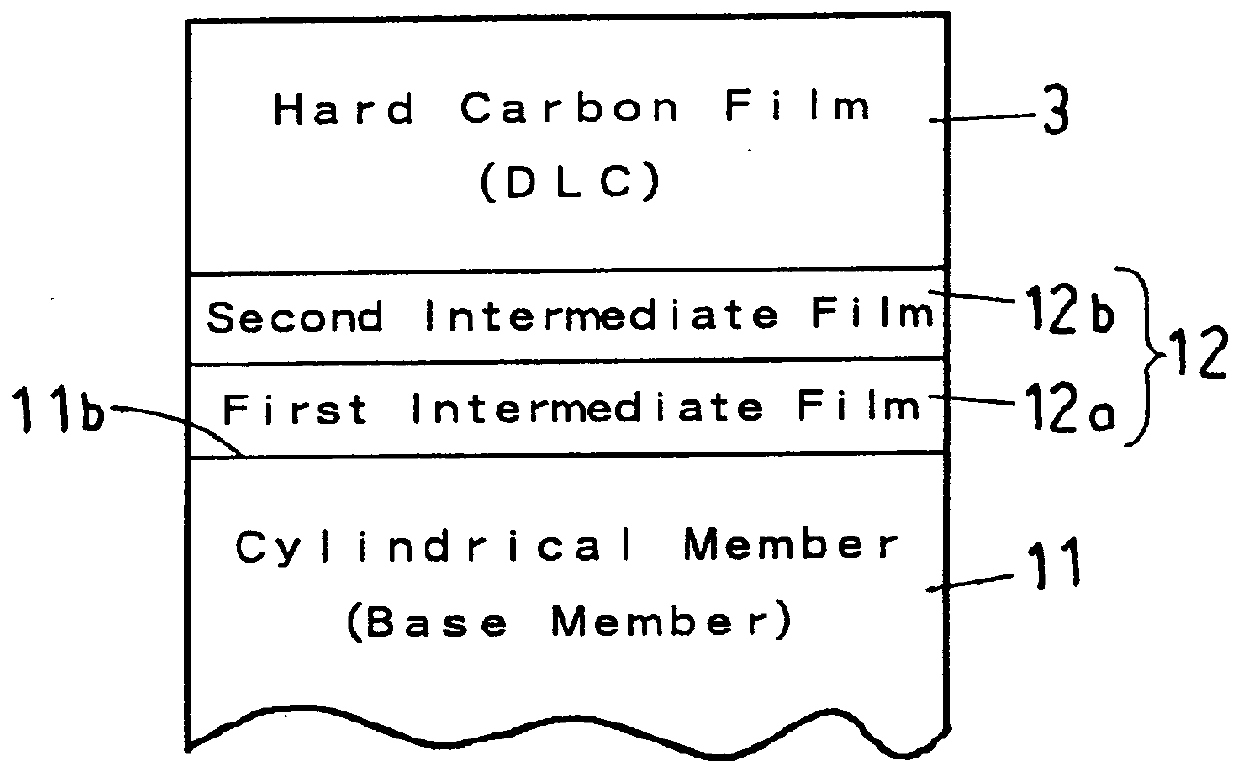
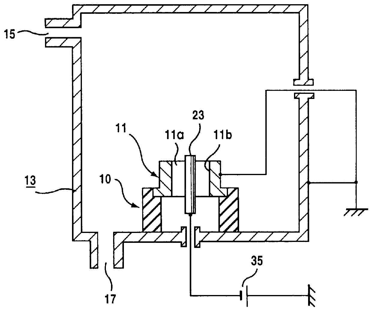
A two-layer intermediate film forming process in Example 3 is similar to that in Example 1. A first auxiliary electrode of a first intermediate film forming material, such as titanium or chromium, is inserted in the center of the bore 11a of the cylindrical member 11 connected to a ground instead of the auxiliary electrode 23 shown in FIG. 6.

A vacuum vessel 13 is evacuated, an AC power source 37 applies an AC voltage to the first auxiliary electrode to evaporate the first intermediate film forming material forming the first auxiliary electrode by resistance heating. The first intermediate film 12a of titanium or chromium having high adhesion with the cylindrical member is deposite...

example 3

is the same in other conditions, functions and effects as the one-layer intermediate film forming process in Example 3 and the two-layer intermediate film forming process in Example 1, and hence further description of Example 2 will be omitted.

In these intermediate film forming processes, the first auxiliary electrode may be made of titanium, chromium, aluminum, a titanium alloy, a chromium alloy or an aluminum alloy, and the second auxiliary electrode may be made of silicon, germanium, a silicon compound or a germanium compound.

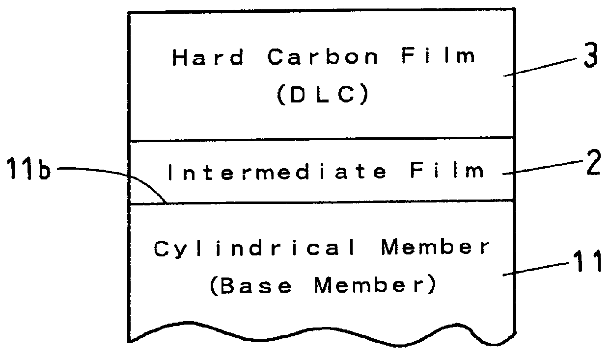
The carbon film 3 shown in FIG. 2 is formed on the two-layer intermediate film 12 formed over the inner surface 11b of the cylindrical member 11 by any one of the hard carbon film forming processes in Examples 1, 2 and 3 after the completion of any one of the two-layer intermediate film forming processes in Examples 1, 2 and 3.

The hard carbon film forming process may be carried out in a vacuum vessel other than that used for carrying out the two-layer interm...

example 4

is the same in other conditions, functions and effects as the two-layer intermediate film forming process in Example 1, and hence further description of Example 4 will be omitted.

Two-Layer Intermediate Film Forming Process in Example 5: FIG. 3

Example 5 differs from Example 4 in that Example 5 forms the second intermediate film of a metal silicide instead of a metal carbide.

The two-layer intermediate film forming process uses the apparatus of FIG. 3, and forms the first intermediate film 12a by the same process as that carried out in Example 4.

After forming the first intermediate film over an inner surface 11b of a cylindrical member 11, a mixed gas of Ar gas, i.e., a sputtering gas, and monosilane gas which is a gas containing silicon, i.e., a monosilane, is supplied through the gas inlet port 15 into the vacuum vessel 13.

The DC power source 35a applies -500 V DC to the auxiliary electrode 23 to produce a plasma around the auxiliary electrode 23 inserted in the bore 11a of the cylin...


PUM

PropertyMeasurementUnit
thicknessaaaaaaaaaa
diameteraaaaaaaaaa
diameteraaaaaaaaaa

Abstract

The present invention relates to a method of forming an intermediate film and a hard cabon film over the inner surface of a cylindrical member having a bore, such as a bushing or a cylinder, with the hard carbon film being formed on the intermediate film with a uniform thickness, greatly enhancing of abrasion resistance of the inner surface. The cylindrical member is placed in a vacuum vessel, an auxiliary electrode of an intermediate film forming material, such as a titanium-silicon alloy or the like, is inserted in the bore of the cylindrical member, a sputtering gas is supplied into the vacuum vessel, a voltage is applied to the auxiliary electrode to produce a plasma around the auxiliary electrode in order that the intermediate film forming material is sputtered from the auxiliary electrode and an intermediate film is formed over the inner surface of the cylindrical member. Subsequently, a gas containing carbon, such as methane gas or the like, is supplied into the vacuum vessel, and a voltage is applied to the cylindrical member to produce a plasma in the vacuum vessel in order that a hard carbon film (DLC film) is formed on the previously formed intermediate film over the inner surface of the cylindrical member.

Description

1. Field of the InventionThe present invention relates to a method of forming films over the inner circumference (surface) of a cylindrical member and, more particularly, to a method of forming a film consisting of a hard carbon film for enhancing the abrasion resistance of the inner surface of a cylindrical member (part), such as a bushing, a cylinder in which a piston reciprocates or a bearing, and an intermediate film (layer) formed between the hard carbon film and the inner surface of the cylindrical member which is capable of sticking to both the inner surface of the cylindrical member and the hard carbon film with high adhesion.2. Description of the Prior ArtA hard carbon film is black and has properties similar to those of diamond. A hard carbon film has advantageous properties including a high mechanical hardness, a small friction coefficient with other materials, a high electrical insulation property, a large thermal conductivity and a high corrosion resistance. Accordingly...

Claims


Application Information

Patent Timeline
Patent Type & Authority Patents(United States)
IPC IPC(8): C23C16/26C23C14/04C23C16/04C23C16/02C23C14/02
CPCC23C14/027C23C14/046C23C16/26C23C16/045C23C16/0281
Inventor SUGIYAMA, OSAMUMIYA, YUKIOKOIKE, RYOTATOIDA, TAKASHISEKINE, TOSHIICHI
Owner CITIZEN WATCH CO LTD
Why Eureka
Try Eureka