Continuous gas saturation system and method

a gas saturation system and continuous technology, applied in the direction of chemical vapor deposition coating, combustion air/fuel air treatment, machines/engines, etc., can solve the problem that the chemical vapor concentration change in the carrier gas concentration cannot be compensated by the cooling system alone, and the chiller unit alone cannot provide complete temperature control

Inactive Publication Date: 2000-10-24
AIR LIQUIDE AMERICA CORP
View PDF12 Cites 56 Cited by
  • Summary
  • Abstract
  • Description
  • Claims
  • Application Information

AI Technical Summary

Problems solved by technology

If, however, the temperature drops, a portion of the chemical vapor condenses from the vapor state, resulting in a change in the concentration of the chemical vapor in the carrier gas.
It has been found, however, that a chiller unit alone does not provide complete temperature control.
Because the chiller unit only provides cooling duty, this additional heat removal cannot be compensated for by the cooling system alone.
With such mechanical devices, however, th...

Method used


Image

  • Continuous gas saturation system and method
  • Continuous gas saturation system and method
  • Continuous gas saturation system and method

Examples


Embodiment Construction

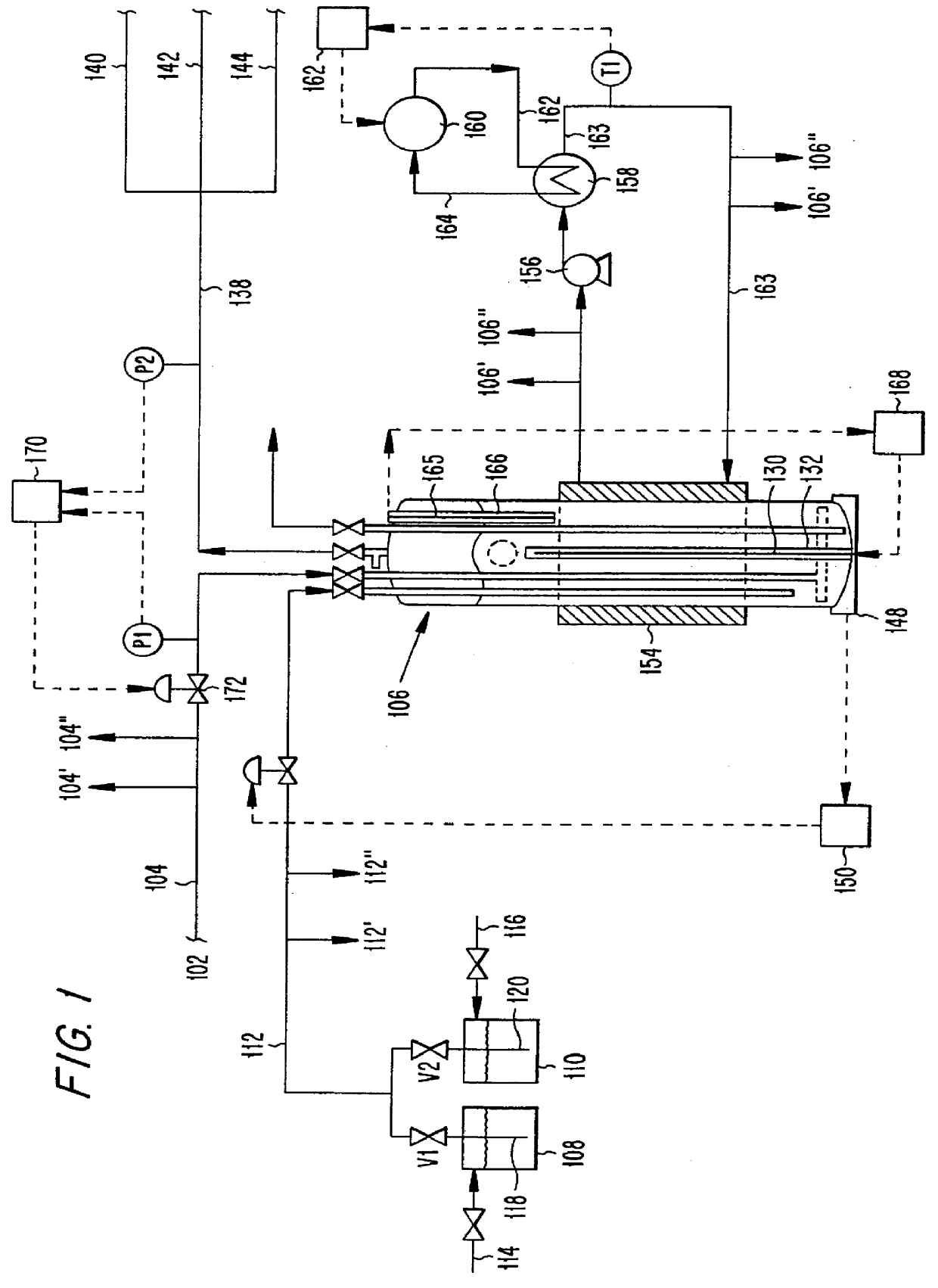
The invention will now be described with reference to FIG. 1, which illustrates an exemplary process flow diagram for gas saturation in accordance with one aspect of the invention.

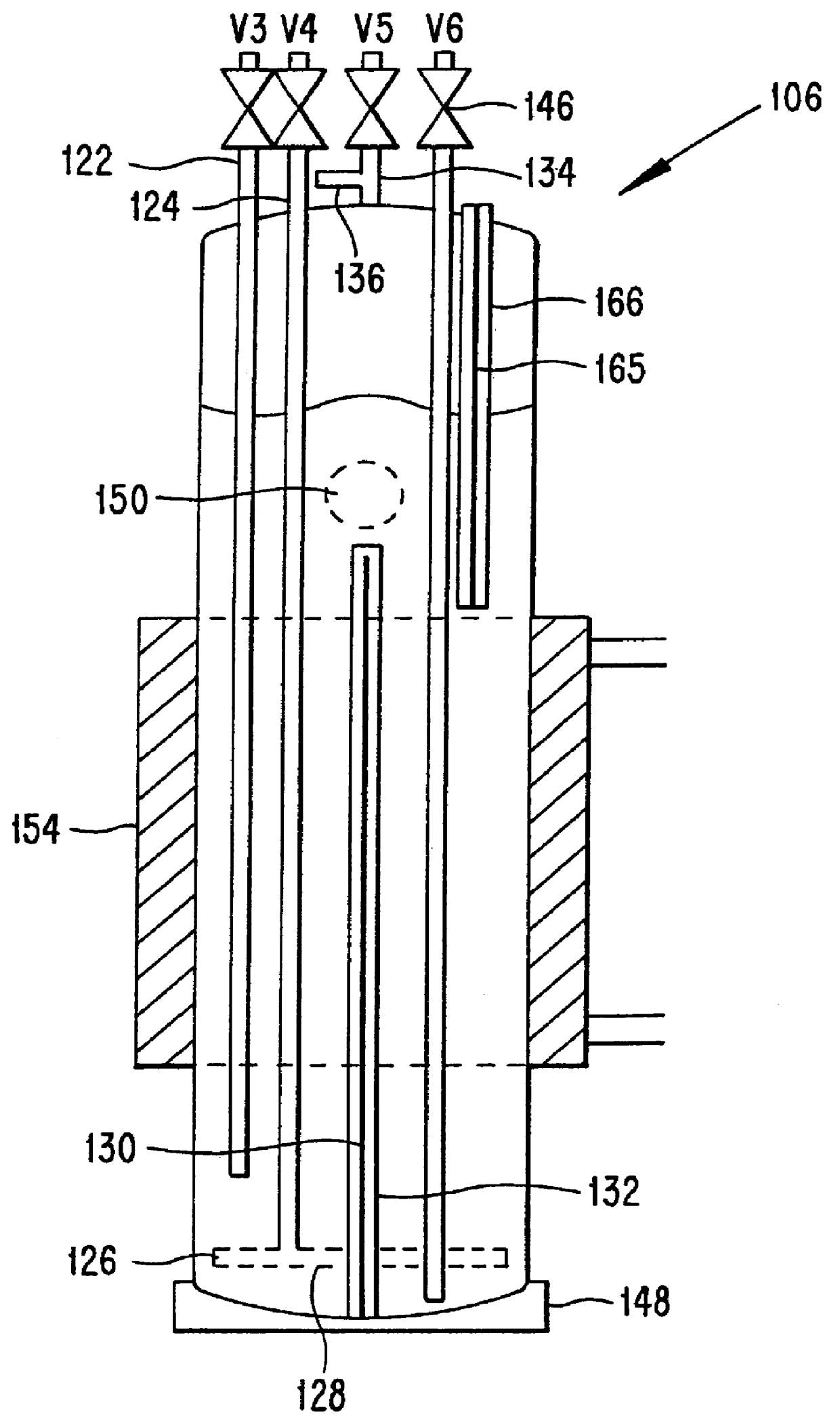
A carrier gas is delivered from a carrier gas source 102 through line 104 to a saturation vessel or bubbler 106, which contains a volatile liquid chemical. The carrier gas is bubbled through the liquid chemical in the saturation vessel 106 to form a saturated gas of desired concentration. The carrier gas source 102 can be, for example, a gas cylinder or a bulk storage vessel.

The specific carrier gas and liquid chemical employed will depend on the end use of the formed saturated gas. Typically, the carrier gas is hydrogen (H.sub.2) or an inert gas such as helium (He), Argon (Ar) or nitrogen (N.sub.2). Other reactive or non-reactive gases can also be used.

The liquid chemical employed in the present invention should be of sufficient volatility that a carrier gas bubbled therethrough can become saturated with ...


PUM

PropertyMeasurementUnit
Temperatureaaaaaaaaaa
Weightaaaaaaaaaa
Pressureaaaaaaaaaa

Abstract

Provided are a system and method for saturating a gas with a vapor from a liquid chemical. The system includes: (a) a saturation vessel connected to receive a liquid chemical and a carrier gas; (b) a gas sparger in the saturation vessel for sparging the carrier gas into the liquid chemical; (c) means for maintaining the liquid chemical in the saturation vessel at a substantially constant level; (d) means for controlling the temperature of the liquid chemical in the saturation vessel to a desired value, comprising (I) a system for cooling the liquid chemical, and (ii) a heater inside the saturation vessel extending vertically in the liquid a distance at least half of the height of the liquid chemical level for heating the liquid chemical; and (e) means for controlling the pressure of the saturated gas to a desired value. The invention also relates to novel methods and systems for controlled delivery of a vaporized liquid chemical. The invention has particular applicability to the semiconductor manufacturing industry.

Description

1. Field of InventionThe present invention relates to novel systems and methods for saturating a gas with a vapor from a liquid chemical. The invention also relates to novel systems and methods for controlled delivery of a vaporized liquid chemical. The invention has particular applicability to the semiconductor manufacturing industry.2. Description of the Related ArtIn the semiconductor manufacturing industry, high purity gases are supplied to process tools for carrying out various semiconductor fabrication processes. Examples of such processes include diffusion, chemical vapor deposition (CVD), etching, sputtering and ion implantation. The use of volatile liquids as the reactant source for these processes is known. Such liquids include, for example, silane (SiH.sub.4) dichlorosilane (SiH.sub.2 Cl.sub.2), trichlorosilane (SiHCl.sub.3), ammonia (NH.sub.3), boron trichloride (BCl.sub.3), chlorine (Cl.sub.2), hydrogen chloride (HCl) hydrogen fluoride (HF) and chlorine trifluoride (ClF...

Claims


Application Information

Patent Timeline
IPC IPC(8): C23C16/448H01L21/223C23C16/44H01L21/205H01L21/265H01L21/31
CPCC23C16/448Y10S261/29C23C16/4485
Inventor NURMI, DOUGLAS B.
Owner AIR LIQUIDE AMERICA CORP
Why Eureka
Try Eureka