Method and apparatus for metering multiple injection pump flow

Inactive Publication Date: 2000-10-24
OILQUIP
View PDF15 Cites 46 Cited by
  • Summary
  • Abstract
  • Description
  • Claims
  • Application Information

AI Technical Summary

Problems solved by technology

Such systems are often incapable of providing sufficiently precise control of high pressure catalyst injection.
However, very slight variations in the catalyst injection rate may result in dramatic swings in process temperature and pressure.
Such variations may result from factors such as hysteresis in the reciprocating pump velocities, tolerances in drive pump output flow rate, tolerances in metering valve flow, lack of sufficient repeatability in pump or valve set points and corresponding flow rate, and so forth.
Swings in process conditions resulting from such catalyst injection rate variations can not only lead to the production of poor quality or

Method used


Image

  • Method and apparatus for metering multiple injection pump flow
  • Method and apparatus for metering multiple injection pump flow
  • Method and apparatus for metering multiple injection pump flow

Examples


Example

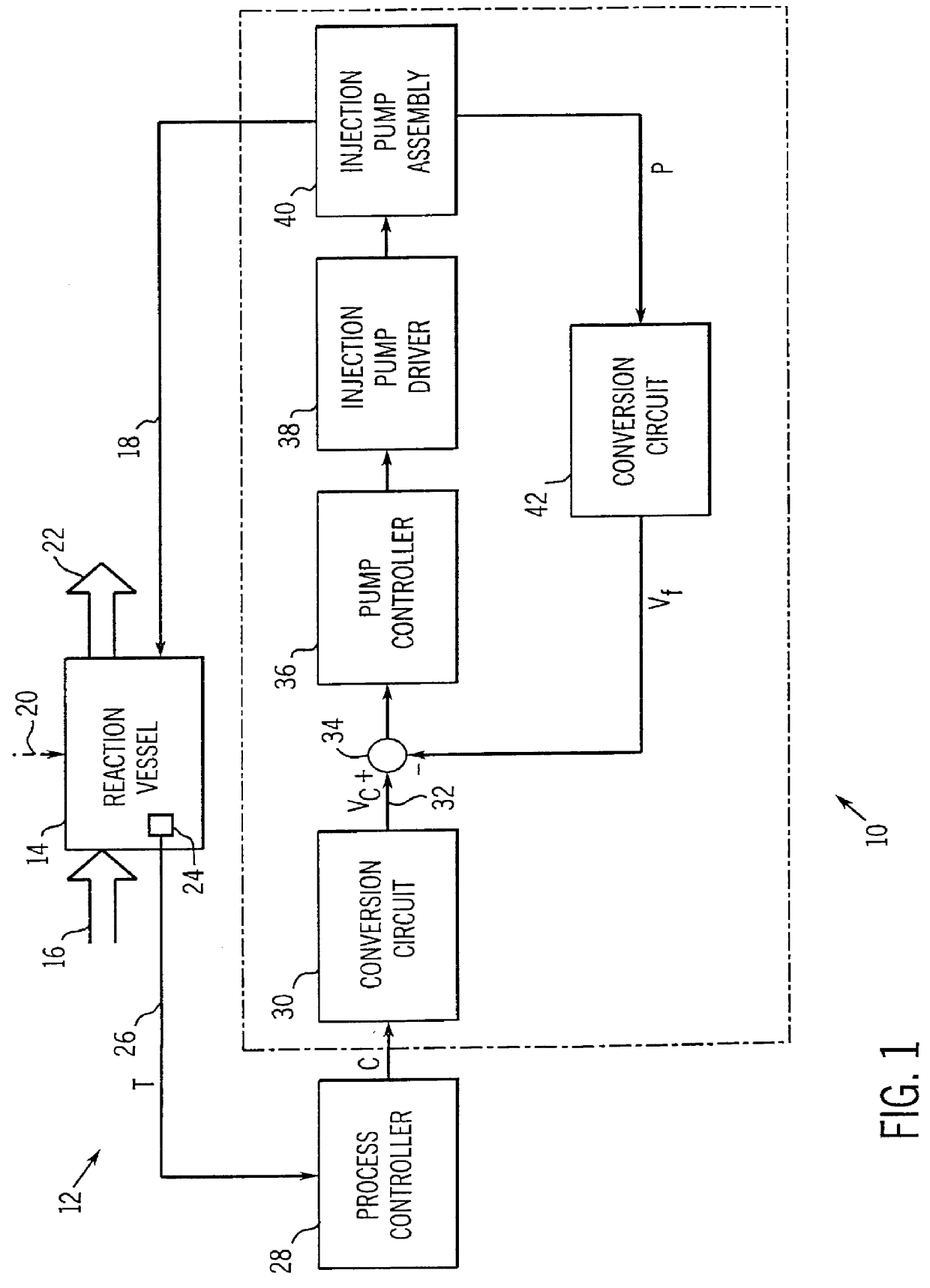
Turning now to the drawings, and referring first to FIG. 1, an injection or metering system, designated generally by reference numeral 10 is illustrated coupled to a process plant 12. As will be appreciated by those skilled in the art, process plant 12 may comprise a variety of industrial chemical process equipment, including pumps, valves, transfer conduits, and so forth for combining or refining specific chemical substances to produce a desired intermediate or final product. In particular, process plant 12 may include polymerization equipment used to produce polymer chains, such as polyethylene, polypropylene and so forth. Plant 12 includes a reaction vessel 14 which receives a process stream 16 of substances to be combined or refined therein. Vessel 14 also receives a flow of metered catalyst 18 used to facilitate or promote the desired reaction within vessel 14. As will be also be appreciated by those skilled in the art, the particular catalyst utilized within vessel 14 and the ...


PUM


Abstract

A system is provided for closed-loop control of a plurality of metering pumps driven by a single source of pressurized fluid. Feedback signals are generated that are proportional to output flow rate from each metering pump, such as velocity of a movable element of the pump with respect to a stationary element. Flow control valves are coupled between the source of pressurized fluid and the metering pumps. A controller receives the feedback signals and regulates flow from the flow control valves to each metering pump to maintain a desired level of output flow. The source of pressurized fluid may include a pressure compensated positive displacement pump having a maximum output flow rate at least equal to the anticipated combined flow rate of drive sections of the metering pumps.

Description

1. Field of the InventionThe present invention relates generally to the field of injection pumps and metering devices, particularly for high pressure fluids, such as chemicals and catalysts. More particularly, the invention relates to a technique for metering the flow from a series of reciprocating injection pumps at precise rates based upon closed-loop control of a parameter closely related to actual flow from the injection pump.2. Description of the Related ArtMany industrial processes require the injection of fluids at very precise rates. For example, in the manufacture of synthetic plastics and other chemical products, high pressure catalysts are injected into process streams to facilitate or accelerate chemical reactions. Because the chemical compositions of the catalysts are often critical to the promotion of the large scale chemical reactions occurring in such processes, their carefully controlled injection into the process stream is often key to obtaining consistent, high qu...

Claims


Application Information

Patent Timeline
IPC IPC(8): F04B49/06F04B9/113F04B9/00F04B13/00
CPCF04B9/113F04B13/00F04B49/065F04B2207/03F04B2205/09
Inventor YODER, PERRY D.HINE, KENNETH W.
Owner OILQUIP
Why Eureka
Try Eureka