
Integral membrane layer formed from a photosensitive layer in an imageable photoresist laminate

a technology of photoresist laminate and integrated membrane, which is applied in the direction of auxillary/base layers of photosensitive materials, photosensitive materials, instruments, etc., can solve the problem that the thin integral layer is not inherently removable from the second layer, and achieves the improvement of product quality and processability, easy peeling, and improved layer differentiation

Inactive Publication Date: 2000-10-31
IKONICS CORP
View PDF18 Cites 26 Cited by
  • Summary
  • Abstract
  • Description
  • Claims
  • Application Information

AI Technical Summary

Benefits of technology

A substantial improvement in product quality and processability can be obtained if an integral layer is formed in the photosensitive laminate structure using a process which involves combining a support film with a first relatively thinner (compared to later formed layers) photosensitive layer and a second relatively thicker (compared to the first layer) photosensitive layer. In this structure the thin and thick 
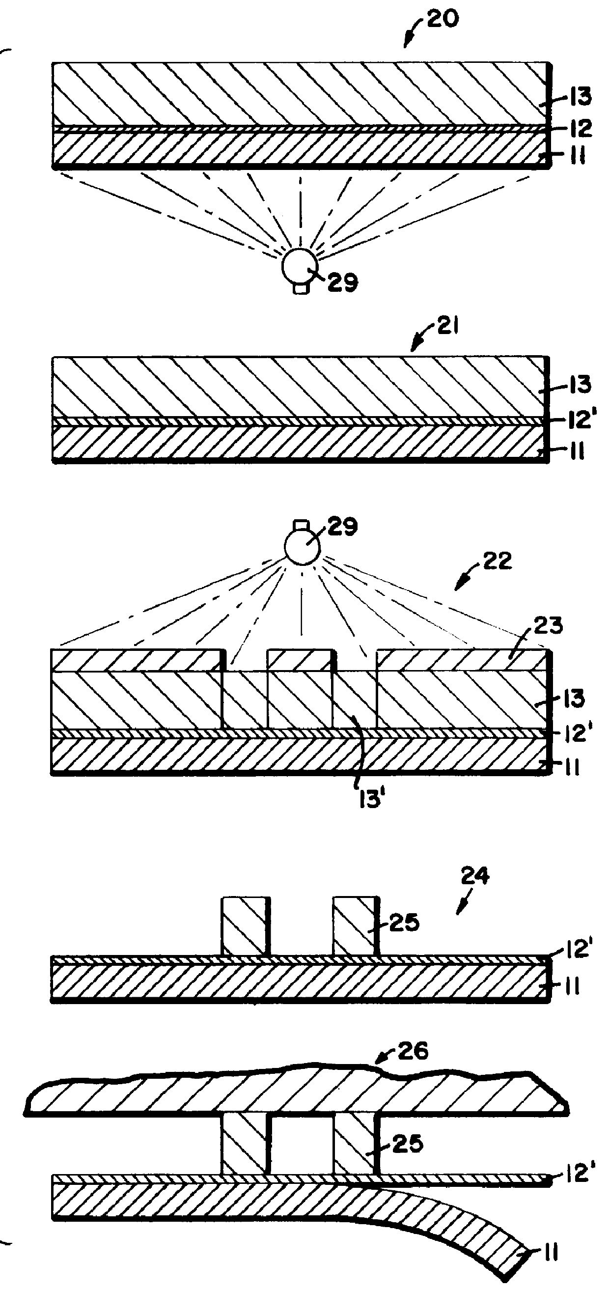
layers can have any order and other intermediate layers can be formed. After the formation of the three layer structure, the structure can be exposed actinic radiation to form an integral membrane layer such that only the thinner photosensitive layer is exposed and rendered substantially less soluble than the thicker photosensitive layer. Preferably the radiation is directed against the substrate or film layer side under controlled conditions to expose only the thinner layer. The thin integral layer formulation and its separate formation as a layer causes the layer to be easily peelable from the substrate. The substrate is typically removed before surface modification of the object. This thin integral layer is not inherently removable from the second layer. The layer is typically removed by abrasion during surface modification (e.g.) sand blasting operations. The imageable second layer is ultimately removed after image formation on a surface. For the purposes of this application, the term "substrate" typically refers to a film or other thin typically substantially transparent layer upon which the photoimageable layers are formed. The term "surface" typically refers to an object surface that is modified, blasted, etched, etc., using a process like sandblasting with a mask formed from the photoimaged laminate structure of the invention. Solubility refers to solubility of the resist layers in the aqueous media commonly used to develop the resist. "Image" and "image transfer" refers to the image formed in the photosensitive layer. "Surface modification" refers to the use of the image in the developed laminate to transfer the developed image onto the surface. Forming the integral layer in a process having at least two coating processes forming a defined integral layer improves differentiation of the layers and also defines the thickness of the integral layer. The freedom of formulation for the peelable layer permits use of formulations that improves peelability at the interface with the substrate and improves overall operations by using formulations optimized for either the thinner layer or the thicker imageable layer. For example colors can be used to identify the layers. The layers can be formulated with different photopolymers, different sensitizers, different amounts of radiation absorbents. These variants modify the photosensitive properties (change .lambda..sub.max, change relative speed, etc.) and improve the ease of differentiation between layers.
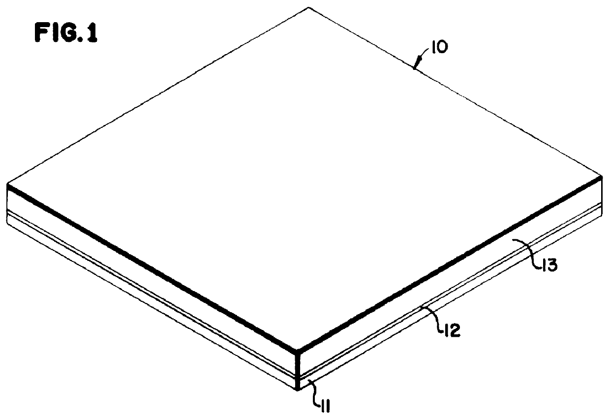
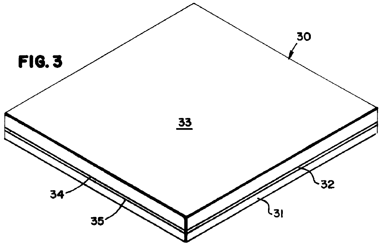
These aspects of the invention can be embodied in one of two structures. In one structure, a support layer is directly coated with the first thinner photosensitive layer and upon the first thinner photosensitive layer is coated the second relatively thicker photosensitive layer. Alternatively, the structure of the three layer laminate of the invention can comprise a support or carrier layer. Directly coated onto the carrier layer can be the second relatively thicker photosensitive layer followed by a relatively thinner photosensitive layer. Either or both of these structures can have other functional layers formed in or on the laminate structures to improve processability, photoimaging, or surface modification.
In each aspect of the invention, after etching is complete and a pattern is fully formed on a surface of an object, the remaining imaged portions of the laminate can be removed either mechanically or chemically from the surface of the object by gentle cleaning. The preferred mode of image formation is sandblasting in which a high velocity abrasive particulate etchant is directed typically in an air blown mode against a masked surface of the object for image formation. For the purpose of this application, the term "integral membrane" indicates a membrane made by exposing a photoresist sheet to a proper amount of electromagnetic radiation for a specific period of time to produce a controllable integral membrane layer in the imaged photoresist sheet. The integral membrane when exposed to solvent by the use of a wash-out process, the integral membrane remains intact and greatly enhances the amount of detail available for transfer. In the application, the integral membrane is made by a coating process that coats a membrane layer in combination with the photosensitive layer. The appropriate exposure of the integral membrane layer to actinic radiation can produce a layer that is more insoluble than the photoresist layer forming the useful integral membrane layer that provides benefits during processing of the imaged film.

Problems solved by technology

This thin integral layer is not inherently removable from the second layer.

Method used


Image

  • Integral membrane layer formed from a photosensitive layer in an imageable photoresist laminate
  • Integral membrane layer formed from a photosensitive layer in an imageable photoresist laminate
  • Integral membrane layer formed from a photosensitive layer in an imageable photoresist laminate

Examples


example 1

The following table 1(A) and 1(B) provide formulations for the first relatively thin layer and the second relatively thicker layer.

TABLE 1(B)

The following table 2(A) and 2(B) provide formulations for the first relatively thin layer and the second relatively thicker layer.

TABLE 2(B)

The following table 3(A) and (B) provide formulations for the first relatively thin layer and the second relatively thicker layer.

TABLE 3(B)

The following table 4(A) and 4(B) provide formulations for the first relatively thin layer and the second relatively thicker layer.

TABLE 4(B)

The following table 5(A) and 5(B) provide formulations for the first relatively thin layer and the second relatively thicker layer

TABLE 5(B)

The following table 6(A) and 6(B) provide formulations for the first relatively thin layer and the second relatively thicker layer. The thicker photosensitive layer having pressure sensitive properties.

TABLE 6(B)

The following table 7(A) and 7(B) provide formulations for the first relatively th...


PUM

PropertyMeasurementUnit
Lengthaaaaaaaaaa
Thicknessaaaaaaaaaa
Thicknessaaaaaaaaaa

Abstract

An integral membrane can be formed in sheet-like photosensitive laminate structures. The process for forming the structure involves coating a first relatively thin photosensitive layer on a substrate or carrier film, then forming a second relatively thicker photosensitive layer (when compared to the first layer) on the first layer. The structure is exposed by directing appropriate actinic radiation against the substrate, film or carrier layer under controlled conditions such that only the first layer is substantially exposed to radiation resulting in polymerization or crosslinking and a substantial reduction in the solubility of the first layer. The relatively thinner less soluble layer then acts as a peelable integral release layer in the photosensitive structure. The thicker second layer can then be imagewise exposed to actinic radiation, and then used conventionally in imaging processes such as sandblasting.

Description

The invention relates to a thin peelable layer in a photosensitive laminate, made by a process using light to form an integral peelable, substantially less water soluble layer, from a photosensitive laminate layer within a three layer photosensitive structure. More specifically, the invention relates to a photosensitive film laminate comprising at least three layers including a carrier or substrate, a peelable, thin photosensitive layer and a thicker imageable photosensitive layer. The layer comprising a peelable photosensitive layer is exposed and rendered less soluble, in an aqueous developer or developing solvent, than a second imageable photosensitive layer in the photosensitive laminate structure. Such second imageable photosensitive layer structure can be imagewise exposed to form an image in the imageable photoresist in a conventional manner. The image can then be transferred to a surface for appropriate surface modification using (e.g.) sandblasting.Photosensitive laminate s...

Claims


Application Information

Patent Timeline
IPC IPC(8): B24C1/00B24C1/04G03F7/038G03F7/095G03F7/38G03F7/40
CPCB24C1/04G03F7/0388G03F7/095G03F7/40G03F7/38
Inventor KOMATSU, TOSHIFUMIGYBIN, ALEXANDER S.JOHNSON, KYLEMACLEAN, DYLAN E.
Owner IKONICS CORP
Learn More