Railcar track cleaning system

a technology for cleaning systems and railcars, applied in railway cleaning, rail wetting/lubrication, rail lubrication, etc., can solve the problem of reducing the energy level of water spray discharged by any one set of nozzles, and achieve the effect of reducing the energy level of discharge, efficient and effectiv

Inactive Publication Date: 2000-11-21
CAROLINA EQUIP & SUPPLY
View PDF22 Cites 47 Cited by
  • Summary
  • Abstract
  • Description
  • Claims
  • Application Information

AI Technical Summary

Benefits of technology

The present invention overcomes the deficiencies of the prior art by providing an efficient, effective and self-contained railcar mounted unit for removing the above indicated types of debris from railroad track systems. The unit employs high pressure water ejected through a variety of nozzles arranged in special arrays to remove leaves, oil and grease, resin coatings deposited by leaves and embedded in porous rail surfaces, snow and ice, and other debris from rails at speeds up to about 30 to 40 miles per hour. A crewman sitting at an operator console located in a cab at the front of the railcar carrying the unit has complete control of the system. The controls provided at this operator station provide for directing water energy onto rail surfaces and other areas of the railway right-of-way, and for reducing the energy of the discharges by shunting water to various combinations of nozzles at intersections and in congested areas.
Operation of each set of nozzles is controlled by a corresponding individual air activated water control or stop valve. Preferably, this water valve is either fully open or fully closed. A solenoid air valve in its open position allows air to pressurize a piston and cylinder assembly mechanically attached as the actuator for this high pressure water valve. The solenoid actuator of the air valve is electrically connected to an on / off switch on the operator console. As the piston in the cylinder extends, the water valve opens to allow water to flow to and through the corresponding set of nozzles. Opening additional water control valves in the same manner allows high pressure water to flow through other sets of nozzles, which reduces the energy level of the water spray discharged by any one set of nozzles. Thus, the more water control valves opened, the less will be the water impact energy available from any one set of nozzles.
Although additional third rail nozzles may be used in each set, the two third rail sets of nozzles are each preferably a single nozzle directed laterally and angled down slightly, preferably 2-15.degree. and more preferably 5-10.degree., to remove snow and ice from an electrified third rail of the type that provides the energy for electric trains. Each third rail nozzle is controlled by a separate air valve. With only one third rail nozzle operating on each side of the railcar, enough water impact energy may be provided to move out of the way medium size tree branches, as well as to provide some leveling of the rail ballast in the areas between the tracks and between the track rails and the third rails.
One of the prior art problems encountered with using compressed air to clear leaves from railroad tracks was that leaves initially blown clear of the tracks would be drawn back onto the tracks by the turbulence created by the railcar motion. The present invention solves this problem by providing for the simultaneous operation of the leaf clearing nozzles and both third rail nozzles. Reducing energy at the leaf clearing nozzles causes less swirling of the leaves, and placement of the third rail nozzles behind the leaf clearing nozzles by a preselected number of feet, depending on the railcar speed, catches the leaves in mid-air and continues to direct them further from the railcar and beyond the reach of its own turbulence.

Problems solved by technology

Opening additional water control valves in the same manner allows high pressure water to flow through other sets of nozzles, which reduces the energy level of the water spray discharged by any one set of nozzles.

Method used


Image

  • Railcar track cleaning system
  • Railcar track cleaning system
  • Railcar track cleaning system

Examples


Embodiment Construction

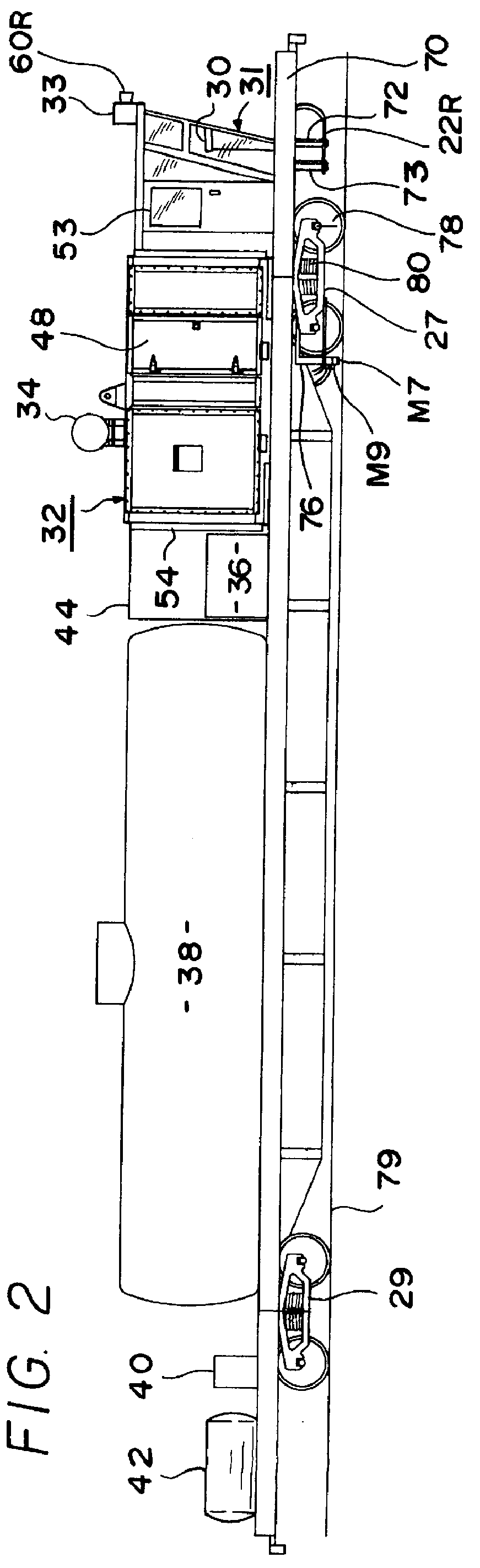
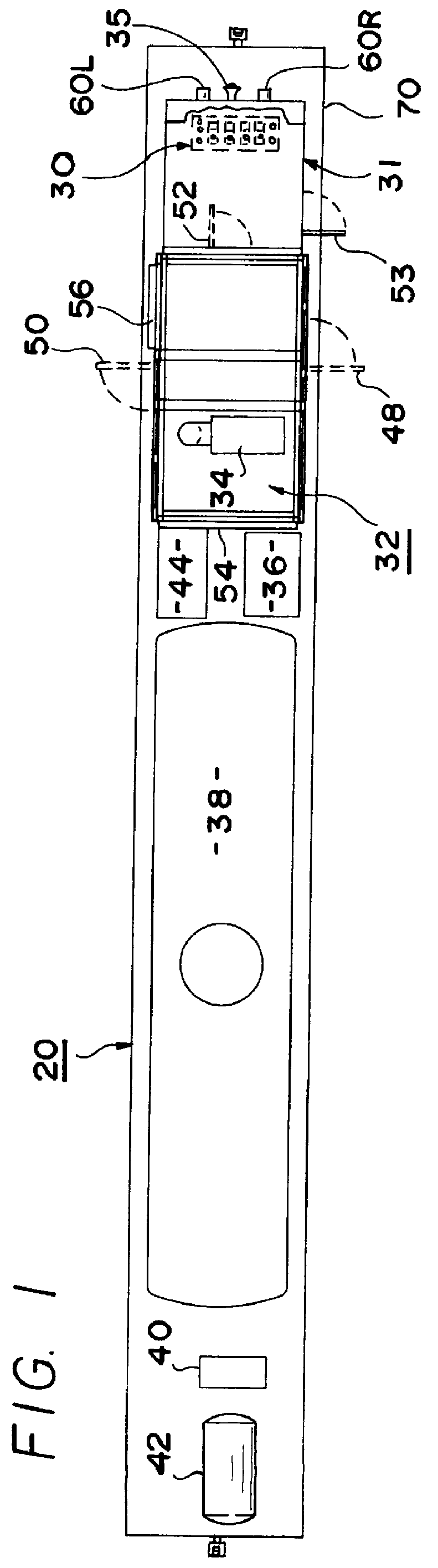
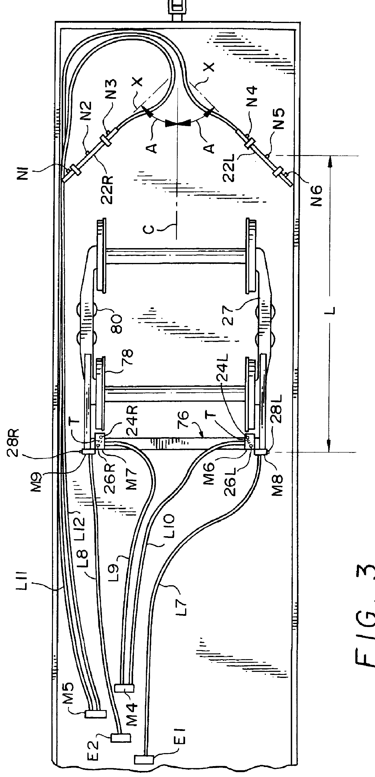
To facilitate a better understanding of the structure and operation of the present invention, reference is made to FIGS. 1-4 in which are shown some of the major components of the invention mounted on the body of a railcar 20. The components shown in these figures include right and left side leaf spray bars 22R and 22L, each carrying three (3) nozzles N1-N3 and N4-N6, respectively, a pair of right side track rail cleaning nozzles 24R and 26R and a pair of left side track rail cleaning nozzles 24L and 26L on the front wheel truck 27 of the railcar 20, right and left side third rail cleaning nozzles 28R and 28L also on front wheel truck 27, an operator console 30 in a front operator cab 31, a pump and engine compartment 32 on the roof of which is mounted an engine silencer 34, an engine fuel tank 36, a water storage tank or reservoir 38, an air compressor 40, a compressed air tank 42, and a valve compartment 44.

The pump and engine compartment 32 has a right outside door 48 and a left ...


PUM


Abstract

A track cleaning system mounted on a railcar and comprising track rail cleaning nozzles, leaf removal nozzles and third rail cleaning nozzles. Each of the nozzles may provide a fan-shaped spray pattern diverging to either side of a central axis and having a major axis. For each track rail nozzle, the central axis may be perpendicular to a horizontal top rail surface and the major axis may be perpendicular to the rail surface centerline. For each leaf nozzle, the central axis may be directly downwardly from the horizontal and the major axis may be parallel to an elongated spray bar on which one or more leaf nozzles are mounted. For each third rail nozzle, the central axis may be directed downwardly from the horizontal and the major axis may be positioned vertically. The third rail nozzles may be mounted to the rear of the leaf nozzles to aid in leaf removal. Main water valves are remotely actuated by air to release high pressure water to corresponding sets of nozzles. A pressure control valve controls the pressure of water supplied to the main water valves from a positive displacement, high pressure water pump.

Description

This invention relates to debris removal systems for rail tracks, and more particularly to a railcar mounted system for removing leaves, leaf resins, snow, ice, oil, grease and other deposits from on and around railroad switches and railroad tracks.Loss of adhesion between the wheels of railroad locomotives and the rails on which the locomotives ride may be caused by the accumulation of leaves, leaf resins, snow, ice, oil, grease and other deposits on the rails. Such deposits may also occur in nearby locations from which they may be blown onto the rails by air currents. Low adhesion conditions require the expenditure of more locomotive power with a corresponding loss in economy, or may seriously reduce the effectiveness of breaking actions of the locomotive and / or the railcars pulled by the locomotive.While sand has been used in the past to increase wheel-to-rail adhesion during slippery rail conditions, the use of sand is both uneconomical and damaging to railroad equipment. For ex...

Claims


Application Information

Patent Timeline
Patent Type & Authority Patents(United States)
IPC IPC(8): B61K3/00E01H8/00E01H8/10
CPCE01H8/105B61K3/00
Inventor CONWAY, RONALD K.BAILEY, DONALD C.
Owner CAROLINA EQUIP & SUPPLY
Why Eureka
Try Eureka