

Method for producing uranium oxide from uranium tetrafluoride and a phyllosilicate mineral
- Summary
- Abstract
- Description
- Claims
- Application Information
AI Technical Summary
Benefits of technology
Problems solved by technology
Method used
Image

Examples
example 1
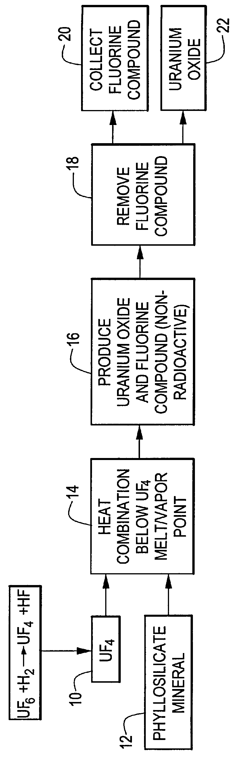
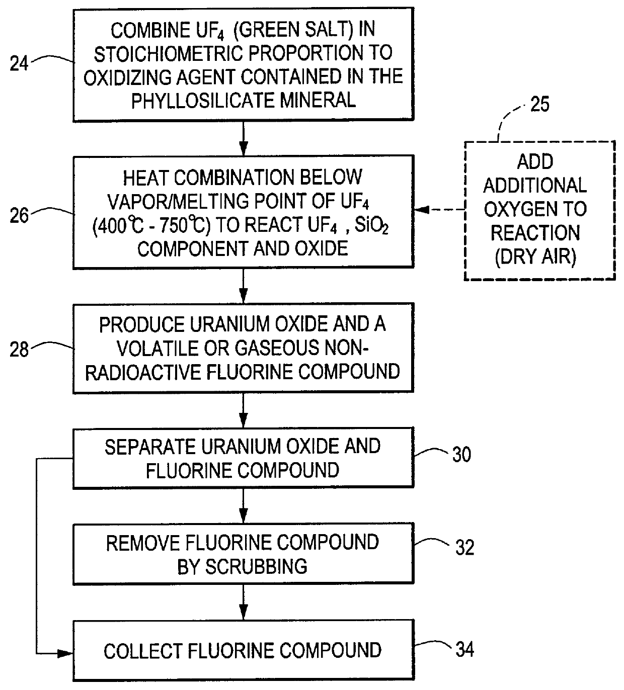
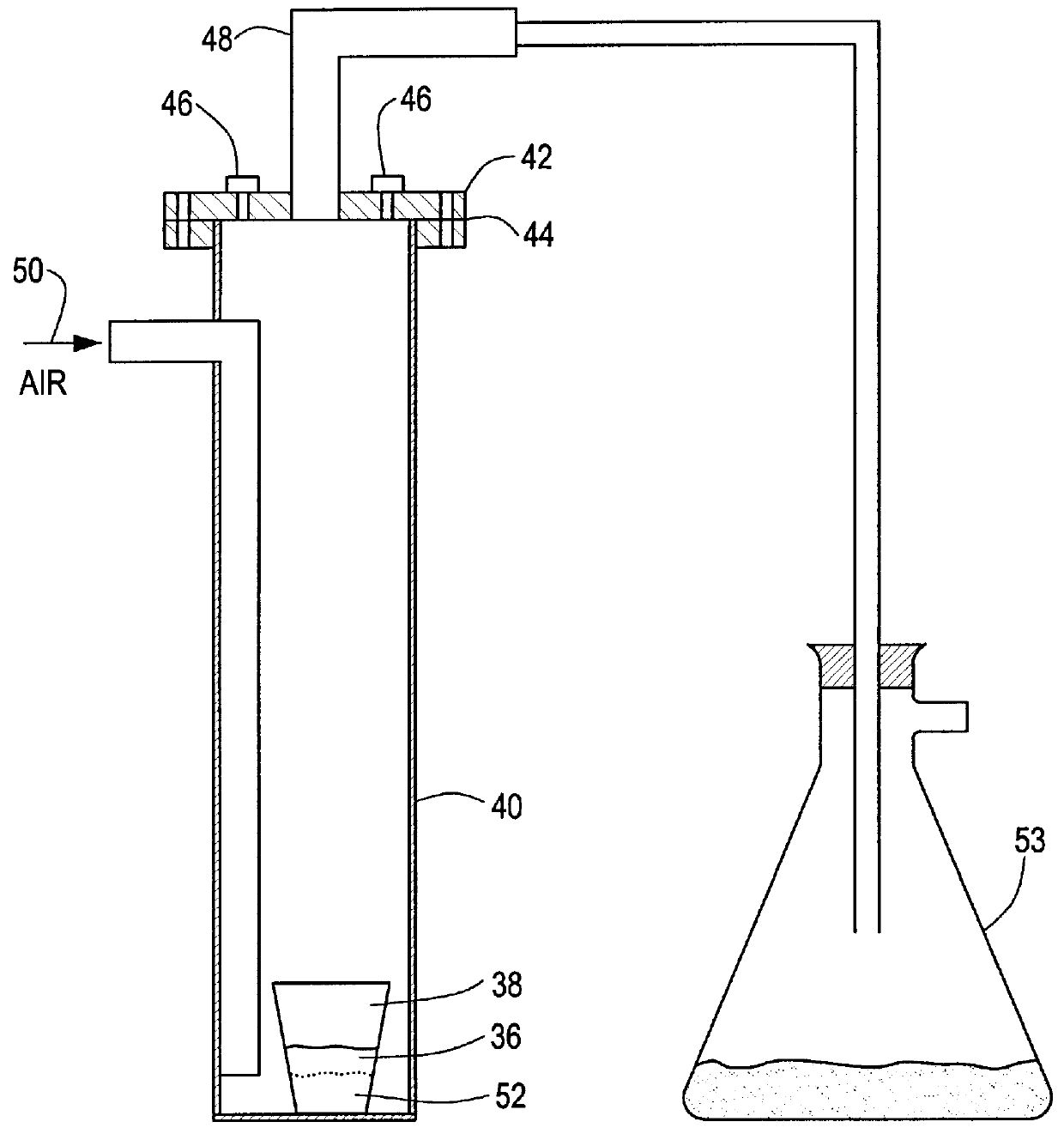
An amount of 19.7 grams of uranium tetrafluoride was combined with 15.2 grams of kaolin. The combination was vigorously shaken for ten minutes to thoroughly mix the constituents. The combination 36, FIG. 3, was transferred to a high density, non-porous, alumina (99.8%) ceramic crucible 38. The crucible was then placed at the bottom of larger vessel 40, made of Haynes.RTM. HR160 alloy and sealed with corrosion resistant cap 42 and teflon gasket seal 44. Cap 42 has inlet ports 46 and outlet port 48 for allowing the gas to flow through vessel 40.
Sealed vessel 40 was placed in a crucible furnace, not shown. For this particular example, inlet ports 46 were capped and a flow of dry air was established through the vessel through side entry inlet 50 at 150-200 cc / min for the duration of the reaction. A second vessel 53 containing sodium fluoride (NaF) for scrubbing the reaction effluent, was connected to outlet port 48.
Vessel 40 was heated to 700.degree. C. in 10.degree. / min. increments and...
example 2
An amount of 31.5 grams of uranium tetrafluoride was combined with 7.0 grams of talc. The combination was vigorously shaken for 10 minutes to thoroughly mix the components. The combination 36 FIG. 3 was transferred to a high density non-porous alumina (99.8%) ceramic crucible 38. The crucible was then placed at the bottom of a larger vessel 40 made of the same material and sealed with corrosion resistant metal cap 42 and ultra high temperature RTV silicon gasket compound. Cap 42 has inlet ports 46 and outlet port 48 for allowing the gas to flow through vessel 40.
Sealed vessel 40 was placed in a crucible furnace, not shown. For this example, a source of dry air was connected to one inlet port 46 with the other inlet remaining capped. A flow of dry air was established through the vessel through port 46 at 150-200 cc / min for the duration of the reaction. A second vessel 53 containing potassium fluoride (KF) for scrubbing the reaction effluent was connected to outlet port 48.
Vessel 40 w...
PUM
 Abstract
Description
Claims
Application Information