

Mold assembly for molding thermoplastic resin and method of manufacturing molded article of thermoplastic resin
a molding method and thermoplastic resin technology, applied in the field of molding molding thermoplastic resin and molding thermoplastic resin molded articles, can solve the problems of poor transfer of the cavity wall of the mold on the surface of the molded article, difficulty in forming the molded article having a surface state similar to that of the mold cavity wall, and difficulty in forming the molded article having defects in appearance, etc., to achieve the effect of improving the flowability of molten thermoplastic resin, reducing residual stress, and improving quality
- Summary
- Abstract
- Description
- Claims
- Application Information
AI Technical Summary
Benefits of technology
Problems solved by technology
Method used
Image

Examples
example 1
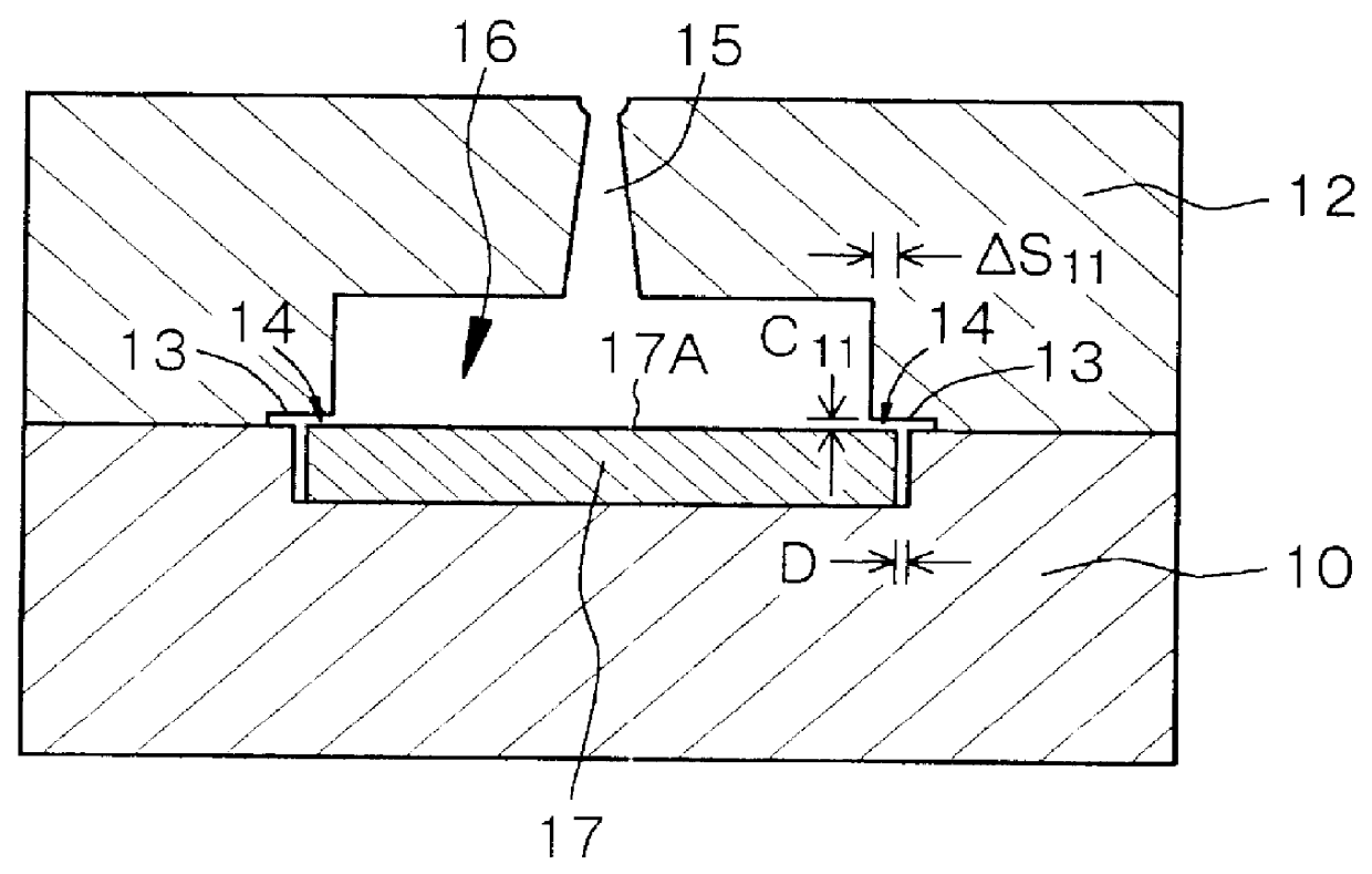
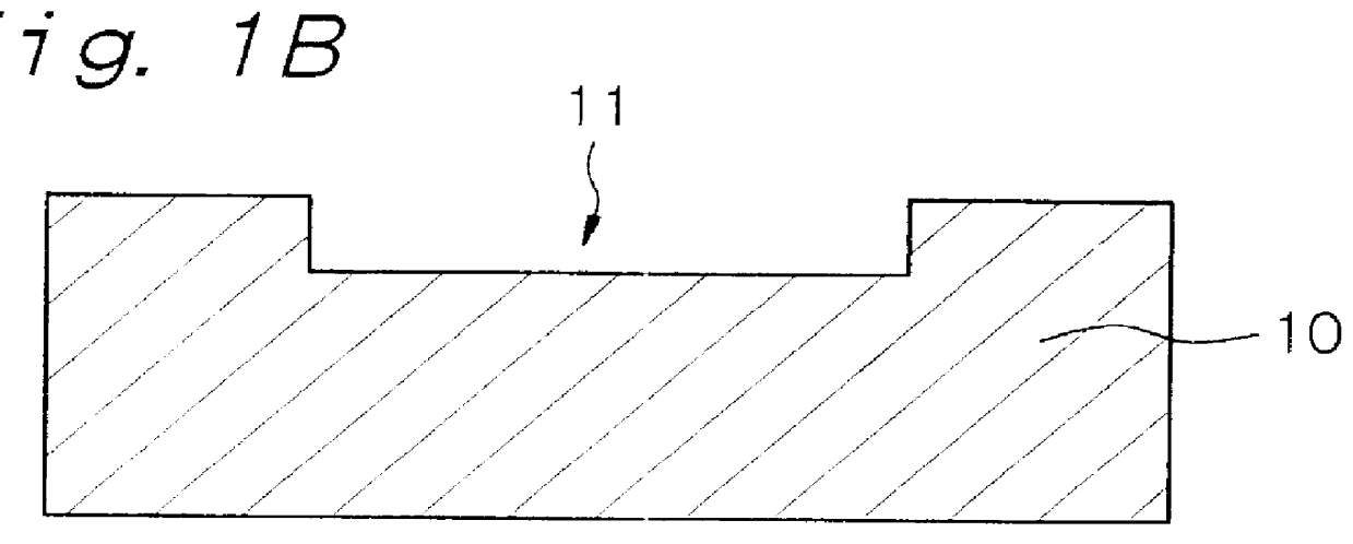
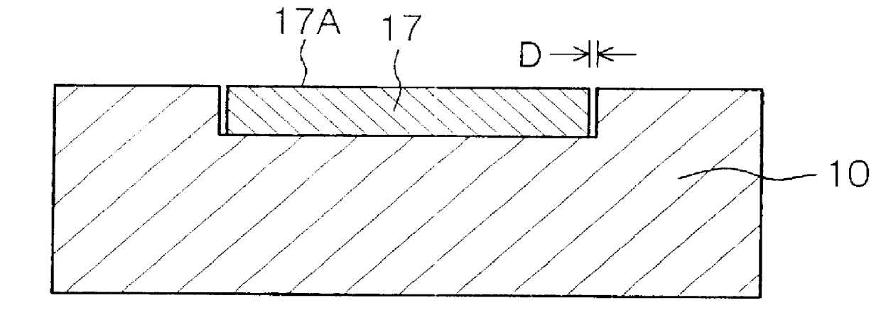
is concerned with the mold assembly for molding a thermoplastic resin, and the method of manufacturing a molded article of a thermoplastic resin, according to the first aspect of the present invention. FIG. 1A shows a schematic cross-sectional view of the mold assembly in Example 1 viewed when it is clamped, and FIG. 2 shows a schematic cross-sectional view of the mold assembly viewed when it is opened. Further, FIGS. 1B and 1C show schematic cross-sectional views of the mold assembly viewed when it is being assembled.
The mold assembly in Example 1 has a first mold member (movable mold member) 10 and a second mold member (fixed mold member) 12 for manufacturing a molded article of a thermoplastic resin, an insert block 17 and a molten thermoplastic resin introduction portion 15 provided in the second mold member 12. The insert block 17 is disposed in the first mold member 10, constitutes part of a cavity 16 and has a thickness of 3.00 mm. An insert block covering portion 14 is forme...
example 2
Example 2 is concerned with the mold assembly for molding a thermoplastic resin, and the method of manufacturing a molded article of a thermoplastic resin, according to the second aspect of the present invention. FIGS. 4A and 4B show schematic cross-sectional views of the mold assembly in Example 2 viewed when it is clamped, and FIG. 6 shows a schematic cross-sectional view of the mold assembly viewed when it is opened. FIGS. 5A, 5B and 5C show schematic cross-sectional views of the mold assembly viewed when it is being assembled. FIG. 4A, 5A, 5B, 5C and 6 show schematic cross-sectional views taken by cutting a cover-plate-including region of the mold assembly with a perpendicular plane. FIG. 4B shows a schematic cross-sectional view taken by cutting a cover-plate-non-including region of the mold assembly with a perpendicular plane in parallel with the above perpendicular plane.
The mold assembly for molding a thermoplastic resin in Example 2 has a first mold member (fixed mold membe...
example 3
used a structure in which the cover plates 33 and 43 provided with the molten thermoplastic resin introduction portion (gate portion) 50 were attached to the first and second mold members 30 and 40, respectively. Alternatively, there may be employed a structure in which a cover plate is attached to one of the first mold member 30 or the second mold member 40.
PUM
| Property | Measurement | Unit |
|---|---|---|
| thickness | aaaaa | aaaaa |
| depth | aaaaa | aaaaa |
| width | aaaaa | aaaaa |
Abstract
Description
Claims
Application Information