Anti-reflection film and display device using the same

a technology of anti-reflection film and display device, which is applied in the direction of television system, photosensitive materials, instruments, etc., can solve the problems of insufficient mass production productivity of the deposition process, inability to finely disperse inorganic particles, and formation of high and low refractive index layers

Inactive Publication Date: 2001-04-03
FUJIFILM CORP
View PDF21 Cites 314 Cited by
  • Summary
  • Abstract
  • Description
  • Claims
  • Application Information

AI Technical Summary

Problems solved by technology

Although the transparent metal oxide layers give an anti-reflection film having excellent optical characteristics, the deposition process has insufficient productivity for mass-production.
However, the inventors noted the problems in forming the layers of high and low refractive indexes.
In forming a high refractive index layer, it is difficult to finely disperse the inorganic particles and further to form the layer having a well dispersed phase.
After forming the layer, they show no functi

Method used


Image

  • Anti-reflection film and display device using the same
  • Anti-reflection film and display device using the same
  • Anti-reflection film and display device using the same

Examples


example 1

Preparation of Titanium Dioxide Dispersion

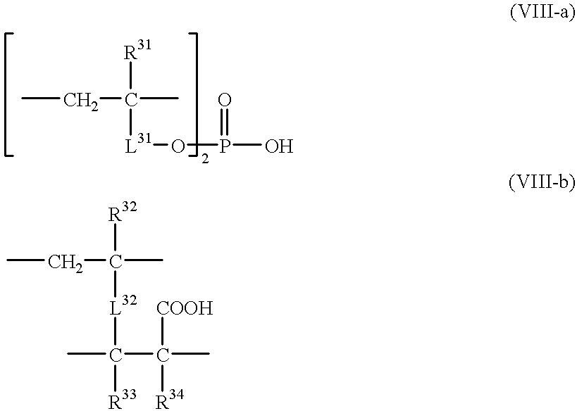
Thirty weight parts of titanium dioxide [weight mean particle size of primary particles: 50 nm, refractive index: 2.70], 3 weight parts of the following anionic monomer (1), 3 weight parts of the following anionic monomer (2), and 64 weight parts of methyl ethyl ketone were mixed by means of a sand grinder to prepare a dispersion of titanium dioxide. ##STR9##

The weight mean particle size of titanium dioxide in the prepared dispersion was determined by means of a coaltar counter. The results are shown in Table 1.

Preparation of Coating Liquid for High Refractive Index Layer

A mixture of dipentaerythritol pentaacrylate and dipentaerythritol hexaacrylate [DPHA, Nippon Kayaku Co., Ltd.], a photopolymerization initiator [Irgacure 907, Ciba-Geigy], a photosensitizer [Kayacure DETX, Nippon Kayaku Co., Ltd.], and methyl ethyl ketone were mixed. The weight ratio of the photopolymerization initiator to the photosensitizer was set at 3 / 1, and the volume ...

example 2

30 weight parts of titanium dioxide [weight mean particle size of primary particles: 50 nm, refractive index: 2.70], 6 weight parts of the following anionic monomer (3), and 64 weight parts of methyl ethyl ketone were mixed by means of a sand grinder to prepare a dispersion of titanium dioxide. ##STR10##

Except for using thus prepared dispersion, the procedure of Example 1 was repeated to produce an anti-reflection film and to evaluate the film. The results are set forth in Table 1.

example 3

30 weight parts of tin oxide [weight mean particle size of primary particles: 10 nm, refractive index: 2.00], 3 weight parts of the anionic monomer (1) in Example 1, 3 weight parts of the anionic monomer (2) in Example 1, and 64 weight parts of methyl ethyl ketone were mixed by means of a sand grinder to prepare a dispersion of tin oxide.

Except for using thus prepared tin oxide dispersion in place of titanium dioxide dispersion, the procedure of Example 1 was repeated to produce an anti-reflection film and to evaluate the film. The results are set forth in Table 1.


PUM

PropertyMeasurementUnit
Particle sizeaaaaaaaaaa
Nanoscale particle sizeaaaaaaaaaa

Abstract

An anti-reflection film comprises a high refractive index layer having a refractive index of 1.65-2.40, and a low refractive index layer having a refractive index of 1.20-1.55. Another anti-reflection film comprises only a low refractive index layer having a refractive index of 1.20-1.55. In the invention, the first improvement resides in a high refractive index layer composed of inorganic fine particles having a mean particle size of 1-200 nm in an amount of 5-65 vol. % and a crosslinked anionic polymer in an amount of 35 to 95 vol. %. The second improvement resides in a low refractive index layer composed of inorganic fine particles having a mean particle size of 0.5-200 nm in an amount of 50-95 wt. % and a polymer in an amount of 5-50 wt. %, and two or more of those particles are piled up to form micro voidsby the adjacent particles.

Description

The present invention relates to an anti-reflection film comprising a high refractive index layer and a low refractive index layer, an anti-reflection film comprising a low refractive index layer, and a display device using the anti-reflection film.PRIOR ARTAnti-reflection films are used in various display devices such as a liquid crystal display device (LCD), a plasma display panel (PDP), an electroluminescence display (ELD), and a cathode-ray tube (CRT). Further, they are generally provided on lenses of glasses or cameras.As the anti-reflection film, a multi-layered film comprising plural transparent metal oxide layers superposed one on another has been widely employed. The plural transparent metal oxide layers reduce reflections of light in a wide wavelength region, and are formed by chemical vapor deposition (CVD) process or physical vapor deposition (PVD) process (especially, vacuum deposition process). Although the transparent metal oxide layers give an anti-reflection film ha...

Claims


Application Information

Patent Timeline
IPC IPC(8): B32B7/02C09D5/00G02B1/11G02B1/10
CPCB32B7/02C09D5/00G02B1/111G02B1/116G02B1/115Y10T428/256Y10T428/259Y10T428/249986G02B1/14G02B1/12
Inventor YASUDA, TOMOKAZUNAKAMURA, KENICHINAKAMURA, TAKUNAKAMURA, KAZUHIRO
Owner FUJIFILM CORP
Why Eureka
Try Eureka