
Convectively cooled, single stage, fully premixed controllable fuel/air combustor

a technology of air combustor and convective cooling, which is applied in the direction of combustion process, turbine/propulsion fuel control, lighting and heating apparatus, etc., can solve the problems of high initial cost, control difficulty, and reduced total

Inactive Publication Date: 2001-04-24
HIJA HLDG
View PDF113 Cites 40 Cited by
  • Summary
  • Abstract
  • Description
  • Claims
  • Application Information

AI Technical Summary

Benefits of technology

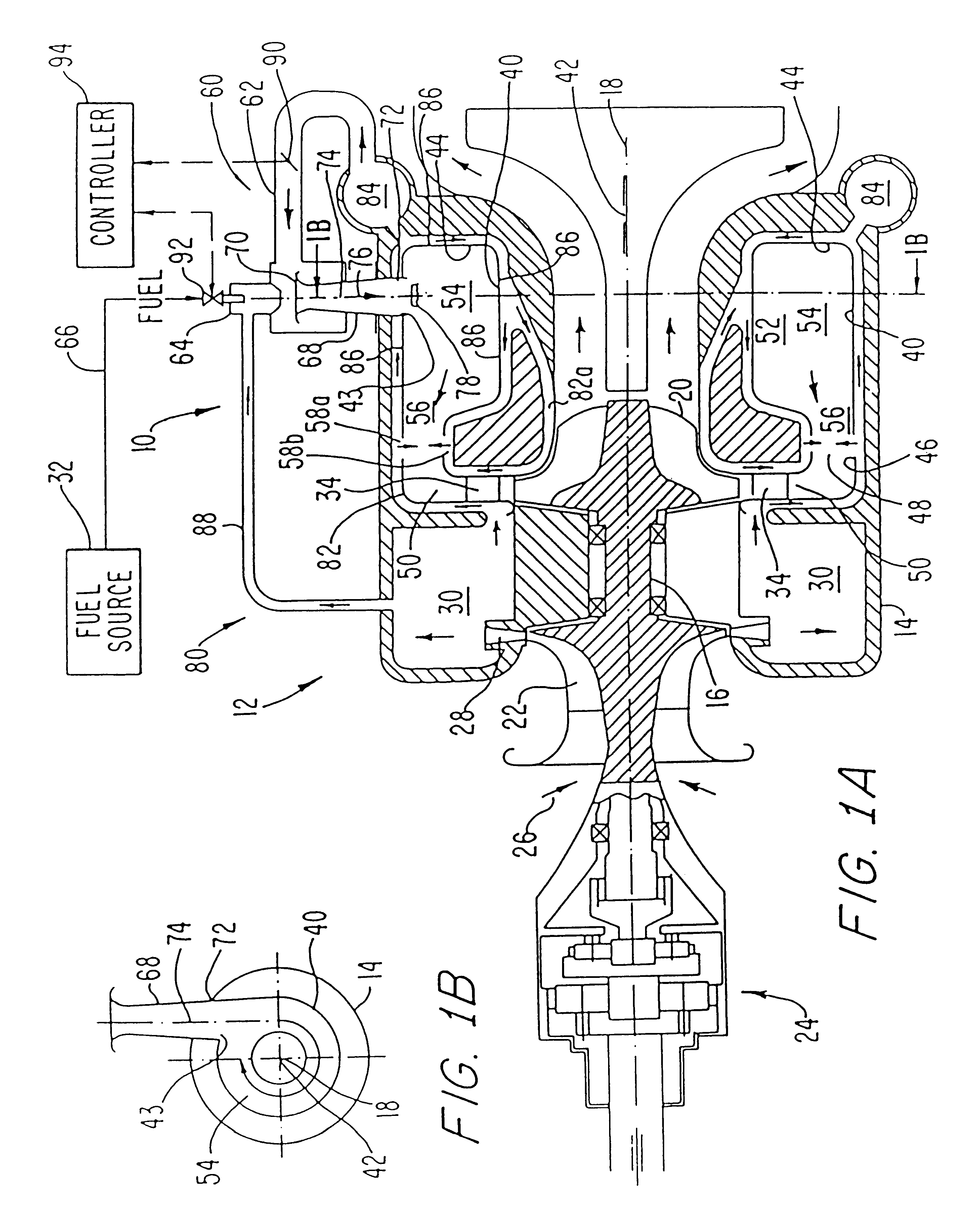
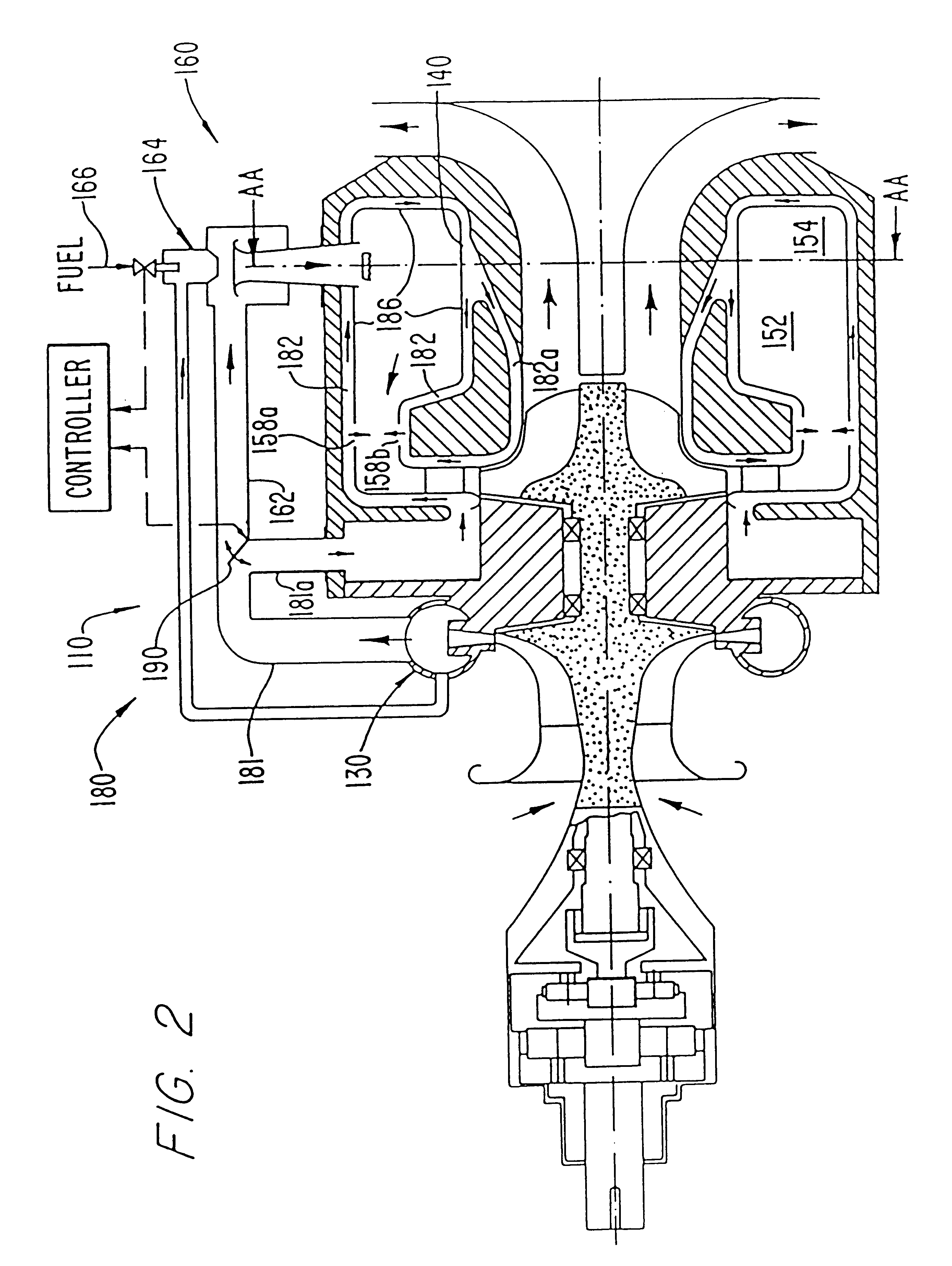
However, certain aspects of the present invention are highly useful even in applications where precise control of the fuel / air ratio afforded by a separate compressed air valve is not needed, as in free-turbine and free-jet propulsion applications. In these applications, control of the compressed air is accomplished automatically by virtue of the dependency of gas generator RPM on fuel flow. Thus, the increased combustion efficiencies and simplicity of construction resulting from the admission of the premixed fuel / air, and the use of substantially all the compressed air flow portion not premixed with the fuel for convective cooling, are significant advantages available for such applications in which a compressed air valve, if included, could be preset to a constant opening or the valve eliminated entirely.
In this invention only one combustion zone is used and the fuel / air ratio and flame temperature will always be high enough to effectively burn the carbon monoxide and hydrocarbons. Therefore, this invention not only produces low emissions of nitrogen oxides, but low emissions of carbon monoxide and unburned hydrocarbons as well by avoiding transition zones between stages of combustion. Since this invention has only one combustion zone, it is not necessary to separate a primary and secondary combustion zone (multistage combustor) or to cool such a separation. Also, it may not be necessary to use a pilot flame or associated apparatus. Furthermore, the control system is vastly simplified by having one fuel control valve which must be precise and, at most, one compressed air control valve for each premixer assembly which is more forgiving where accuracy and leakage are concerned. Additional simplification is possible in certain applications which allow the elimination of the compressed air control valve.

Problems solved by technology

Although gas turbine devices such as engines and gas generators do not produce the majority of the nitrogen oxide emissions released into the earth's atmosphere, reducing those emissions will reduce the total and, in that regard, many countries have enacted laws limiting the amounts that may be released.
However, the complexity of the above constructions employing multiple fuel nozzles and fuel splitting devices can lead to control difficulties, as well as a high initial cost.
Flash backs can adversely affect the mechanical integrity and performance of the premixer system and related structure.
Flow separation can cause flash backs into the premixer.
Pulsations can adversely affect the combustor liner and engine structure.
Each of the above described conditions, if they occur, can adversely affect the mechanical integrity and performance of the gas turbine.
Impingement of the flow onto the liner wall can lead to carbon build up and decrease heat transfer performance and increase thermal fatigue.
However, at this level, the flame is close to extinction and the carbon monoxide emissions are high.
Experience has shown that it is not enough to just limit the average temperature because, when a fuel is burned as drops of liquid or a diffusion gas flame, the combustion proceeds at near the stoichiometric value and the local temperature is very high, thus producing excessive NO.sub.x.
If these requirements are met, combustion cannot occur before the fuel / air mixture leaves the premixing device.
Furthermore, the utilization of essentially the total amount of compressed air flow to either combust the fuel or to dilute the exhaust gases upstream of the turbine provides considerable reduction of peak combustor temperatures resulting in longer life for combustor liners compared to conventional combustor designs.
When the valve opening changes, the pressure drop over the premixer changes, resulting in an increase or decrease of air mass flow.
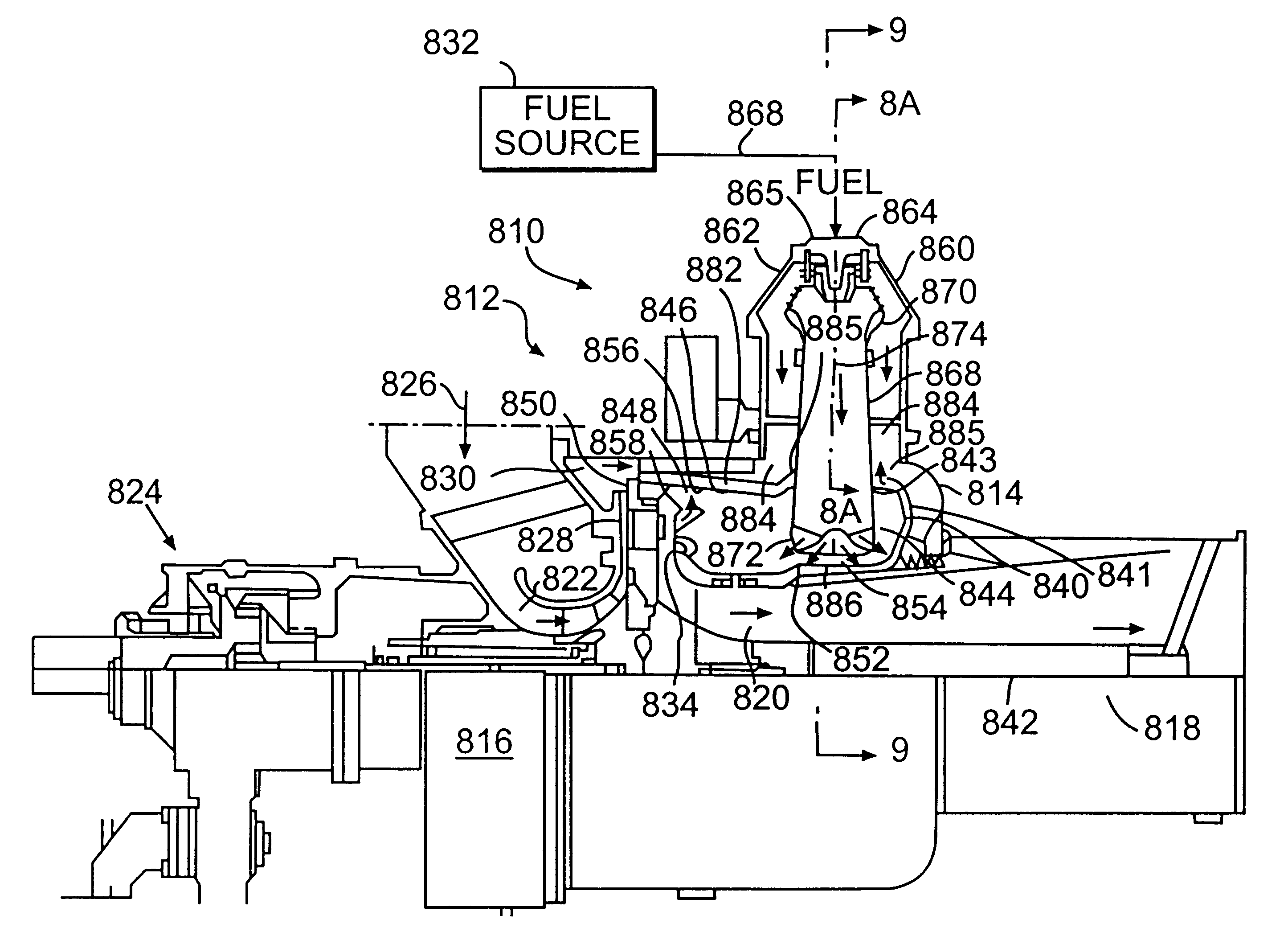
This asymmetric nozzle port arrangement permits more effective utilization of the combustion volume while minimizing fuel / air mixture impingement on the liner wall, which can lead to carbon build up, uneven heat transfer, and increased thermal stress-caused distortions.
Carbon deposits can eventually insulate areas of the liner, causing problems of thermal fatigue and localized overheating of the combustion chamber.

Method used


Image

  • Convectively cooled, single stage, fully premixed controllable fuel/air combustor
  • Convectively cooled, single stage, fully premixed controllable fuel/air combustor
  • Convectively cooled, single stage, fully premixed controllable fuel/air combustor

Examples


Embodiment Construction

In order to assess the performance of the annular combustor system of the present invention, an annular combustor having the fuel / air premixer as shown in FIGS. 3A-3C was atmospherically tested using an external source of air and a gaseous fuel (natural gas). Table 1 presents values of the important dimensions of the apparatus used in the test.

Tests were done at flow conditions corresponding to idle and full load. Flow rates to achieve a preselected fuel / air ratio were set by manually setting compressed air valve 290 and the fuel valve (not shown) rather than by a controller element although a controller element could have been used. Table 2 presents the fuel and compressed air flow rates and other important parameters as well as the measured NO.sub.x levels and approximate CO emission levels for the tests.

The above indicates remarkably low NO.sub.x emission levels which, even if scaled for high pressure operation, still would be well below the values considered representative of st...


PUM


Abstract

A premixer for a combustor system has a venturi-type mixing tube with a flow axis, an inlet adjacent one axial mixing tube end, and a nozzle assembly at the opposite axial mixing tube end. The mixing tube inlet is flow connected to a source of compressed air and a source of fuel, and the mixing tube is connected to combustion chamber, an annular or can-type liner and an inlet, and the nozzle assembly extends into the combustion chamber and has at least one port for distributing the fuel / air mixture within a single stage combustion zone. In a preferred configuration, a pair of premixers are located at diametrically opposed positions on an annular combustion chamber, and the venturi axes are both radially disposed and axially inclined with respect to the combustion chamber axis. A single, centrally located, cylindrical air valve controls compressed air flow to both premixers through a manifold and distribution conduits.

Description

1. Field of the inventionThis invention relates to a combustion system for gas turbine gas generators, gas turbine engines, or other heat devices, which can produce significant advantages including low levels of pollutants, namely oxides of nitrogen, carbon monoxide, and unburned hydrocarbons. In one aspect, the present invention relates to a system, process, and apparatus for combusting fuel in a gas turbine or gas generator module which significantly lowers pollutants by providing a nearly constant fuel / air ratio in the combustion zone at all engine operating conditions in addition to thoroughly premixing the fuel and air prior to combustion and, when necessary, completely vaporizing a liquid fuel. In another aspect, the present invention relates to single stage, controllable fuel / air ratio combustors for gas turbine fuel / air premixer assemblies. In another aspect, the present invention relates to a mixing tube in a premixer chamber for a combustor system having a flow axis, an in...

Claims


Application Information

Patent Timeline
IPC IPC(8): F02C9/00F02C9/50F23R3/42F23R3/02F23R3/28F23R3/50F23R3/54F23R3/00F23R3/34F23R3/26F23R3/10F23R3/30
CPCF02C9/50F23R3/26F23R3/286F23R3/346F23R3/42F23R3/50F23R3/54F05D2250/322
Inventor MOWILL, R. JAN
Owner HIJA HLDG
Learn More