

Optical recording disk
a recording disk and optical technology, applied in the field of optical recording disks, can solve the problems of more serious cross-talk problem, major problem, especially serious,
- Summary
- Abstract
- Description
- Claims
- Application Information
AI Technical Summary
Benefits of technology
Problems solved by technology
Method used
Image

Examples
embodiment 1
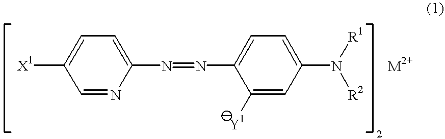
A polycarbonate substrate is prepared which had a thickness of 0.6 mm and comprised a U-shaped guide groove having a groove depth of 150 nm and a groove width (half-height width) of 0.25 .mu.m. AFM measurements showed that a track pitch was 0.80 .mu.m and Lp was 70% of L. A metal-containing azo pigment shown by the following formula: ##STR15##
was spin-coated onto the polycarbonate substrate at 800 rpm. after dissolving 0.06 g azo pigment into 5 g octafluoropentanol (OFP), followed by annealing the azo pigment for an hour in an oven heated at 80.degree. C. to form a recording film. The weight reduction property of the pigment is the type shown in FIG. 3, wherein the weight reduction in the main weight reduction process, temperature difference, weight reduction rate, starting temperature of the main weight reduction process and total weight reduction were 37.1%, 3.6.degree. C., 10.3% / .degree. C., 280.degree. C. and 47%. The thermogravimetric analysis (TGA) was effected by using a diff...
embodiment 2
A bonded disk was fabricated in the present embodiment similarly to Embodiment 1 except for the rotational speed of the substrate during spin-coating of the dye solution, which was 600 rpm. in the present embodiment. Absorbance of the pigment film was measured with a reference of a substrate which was similar to the substrate on which the pigment film was formed, resulting in A1=0.11, A0=0.68, and A1 / A0=0.16. The film thickness d.sub.land of the recording film at the land area was 95 nm, and the groove depth d.sub.film at the recording film was 78% of the groove depth d.sub.sub at the substrate, which corresponded to a film thickness d.sub.film of 128 nm at the groove area. The resultant disk was subjected to recording at a 640 nm wavelength similarly to Embodiment 1, resulting in I.sub.top =60%, I.sub.11 / R.sub.top =70%, and jitter for the minimum mark length of about 0.4 .mu.m being 9ns for the disk. The cross-talk and transformation of the recorded section of the substrate were s...
embodiment 3
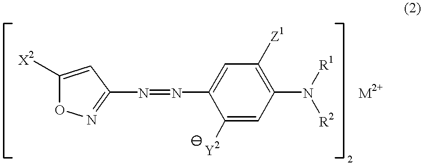
A bonded disk was fabricated in the present embodiment similarly to Embodiment 1 except for the pigment which had a chemical structure expressed as follows: ##STR16##
The refractive index "n" and extinction coefficient "k" of the single-layer pigment were 2.5 and 0.05, respectively, at a 640 nm wavelength. The liquid pigment was spin-coated onto a substrate which had a track pitch of 1.6 .mu.m and a guide groove of 160 nm in depth, annealed at 80.degree. C. for an hour, taken out after cutting, and subjected to measurement of the absorbance with reference to air, which showed an absorbance A1=0.06, A0=0.65, and A1 / A0=0.09 after subtracting the base line absorbance. The film thickness d.sub.land of the recording film at the land area was 80 nm, the groove depth d.sub.film at the recording film in the recorded section was 75% of the groove depth d.sub.sub at the substrate, and accordingly, the film thickness d.sub.groove of the recording film at the groove area corresponded to 120 nm.
T...
PUM
 Abstract
Description
Claims
Application Information