Method for noncoherent coded modulation

a non-coherent code and modulation technology, applied in the direction of coding, amplitude demodulation, code conversion, etc., can solve the problems of difficult to find the exact model of the phase process, difficult to achieve the effect of maximum overlap and convenient decoder implementation

Inactive Publication Date: 2001-05-15
CALIFORNIA INST OF TECH
View PDF3 Cites 53 Cited by
  • Summary
  • Abstract
  • Description
  • Claims
  • Application Information

AI Technical Summary

Benefits of technology

Currently, there is a gap between the performance of coded noncoherent systems and the coherent ones. For example, there is about 3 dB difference in performance on the AWGN channel between constraint length 7 rate 1 / 2, coded PSK and DPSK (differential PSK), even when interleaving is used for the DPSK. Moreover, there is not much available trade-off between bandwidth and power efficiency with currently used noncoherent modulations as it is with coherent ones. Recently it has been shown that the performance of noncoherent detection can be improved by using a longer observation time (one symbol for FSK and two symbols for differential detection). The observation is the time window in which the carrier phase is assumed to be constant. Multiple symbol noncoherent detection of uncoded DPSK and multiple symbol noncoherent detection of uncoded CPM are both well-known. Application to block coded MSK is well-known as is a new block coded MPSK for noncoherent detection. Multiple-symbol differential detection of trellis coded MDPSK is also well-known. Multiple-symbol noncoherent detection of trellis coded modulation has been confined to applications which use differential encoding. Also, no optimization of the code selection has been performed. In all of the above contributions, the observations are independent. In the case of uncoded or block coded modulation, one observation was used for each decision. When convolutional coded modulations were decoded, independent observations were used. In some methods the observations overlap in one symbol and interleaving was used for making them independent. The interleaving function adds extra complexity to the system and causes unwanted delay in the received data, although in some applications such as fading channels, interleaving is required.
The noncoherent decoding of the present invention described below herein can be applied to almost all types of coded modulation, without changing the encoder, and with performance that in general approaches the coherent decoding of these codes as the observation length grows. We also show new codes with high noncoherent performance which are also optimal for coherent decoding (have maximum free distance), and their performance with the efficient noncoherent decoding.
Unlike the previous approaches, we use maximally overlapped observations as illustrated in FIG. 9, which will not and cannot be made independent. We thus utilize the information from all possible (time shifted) observations of length T. When applying this technique to trellis coded modulation, each observation spans several branches of the code trellis. The resulting noncoherent sequence estimator of the invention is described below. The performance of the noncoherent sequence estimator can be shown analytically to approach the performance of the coherent one as the observation length grows and can be applied to many other codes and modulations. This related coded modulation and detection communication system is referred to hereinafter as "Noncoherent Coded Modulation (NCM)" and is illustrated in FIG. 10. It provides tradeoff between robustness with respect to phase variations (or frequency uncertainty) and power efficiency, by controlling the observation length of the detector. The existence of decoding algorithms, whose complexity depends only slightly on the observation length (which will be described hereinbelow) makes this tradeoff efficient. Referring to FIG. 10, the system includes an encoder 1010, a phase shift key modulator 1020, an AWGN channel 1030 having slowly varying phase and a noncoherent maximum likelihood sequence estimator (IO-NMLSE) 1040. NCM may be attractive even in cases where phase synchronization is not a major problem, since its degradation relative to coherent demodulation can be smaller than the degradation caused by imperfect phase estimation.
where S is the observation length in symbols, l (an integer) is the observations spacing in symbols, and for every symbol i, r.sub.i is a complex vector which assumes the output of D complex matched filters, each for one complex dimension of modulation. The sequence of vectors of dimension D, x.sup.(m), is the signal space representation of x.sub.m (t). Let us define L as the number of trellis branches which are covered by one observation, i.e., .left brkt-top.L=S / n.right brkt-top. (assuming l is a multiple of n; or else, in some cases it is necessary to add 1), where n is the number of symbols in a trellis branch. L is more important than S since it determines the complexity of the decoder and also relates more closely to the actual observation time T. Unless stated otherwise, we will use l=n for maximal overlapping and convenient decoder implementation.
If the code is not noncoherently catastrophic (see next section), then as S increases (and the allowed phase variations are reduced appropriately), the performance of the IO-NMLSE approaches that of the MLSE with a completely known phase. This provides a tradeoff between robustness to phase variations and power efficiency.

Problems solved by technology

Digital communication systems used in practical applications are often very complicated.
For example, the receiver for the NASA Deep Space Network took over one decade to develop and cost millions of dollars.
In many cases, it is very difficult to find the exact model of the phase process (also referred as phase noise or phase jitter).
If this is not the case, then communication becomes difficult if not impossible, and large degradation is unavoidable.
constant, the observation length is T.sub.b log.sub.2 M. For a large M, the assumption made that the phase is constant over the length of the symbol may no longer be satisfied, so it is not useful over practical channels.

Method used


Image

  • Method for noncoherent coded modulation
  • Method for noncoherent coded modulation
  • Method for noncoherent coded modulation

Examples


example 14.1

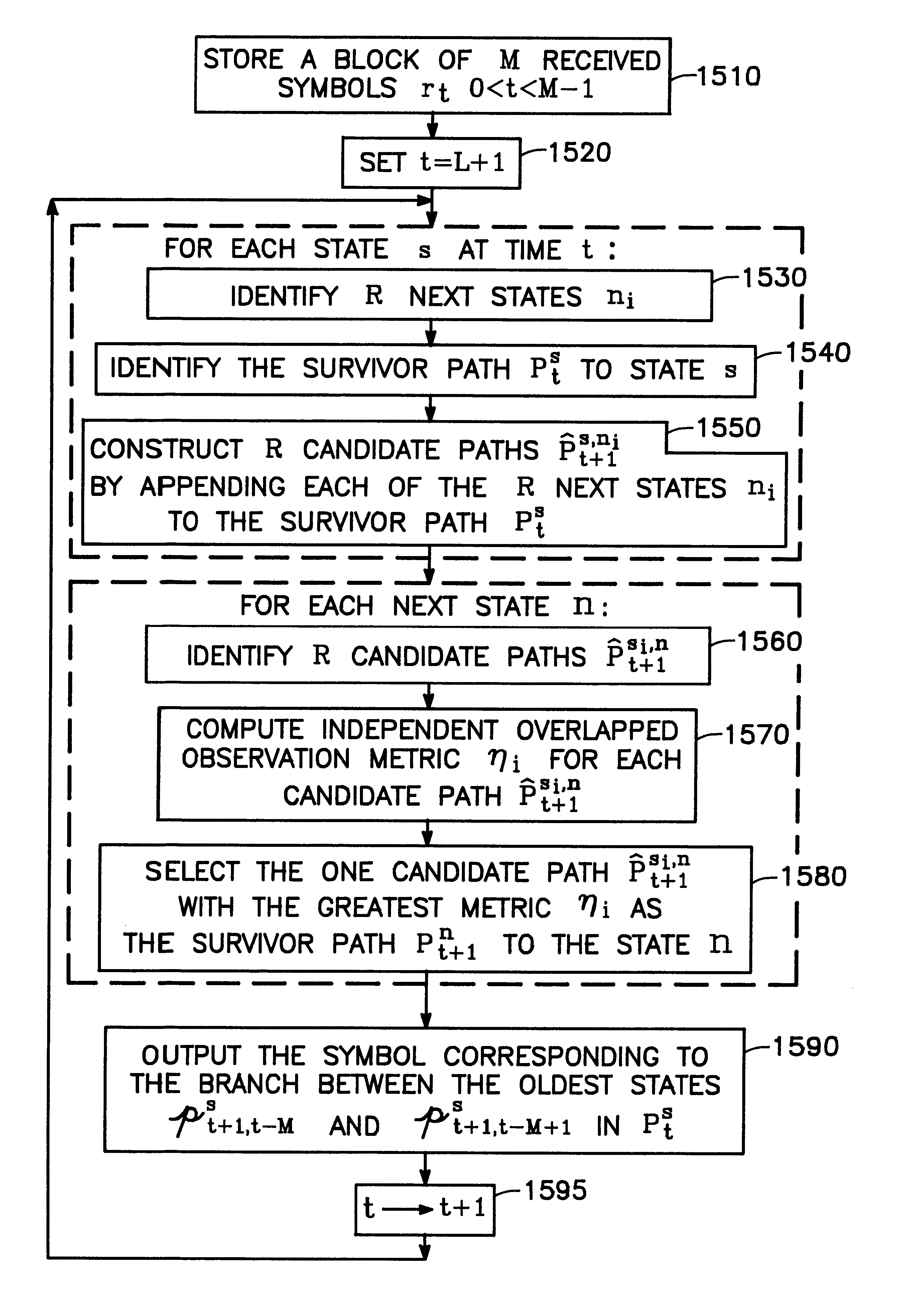
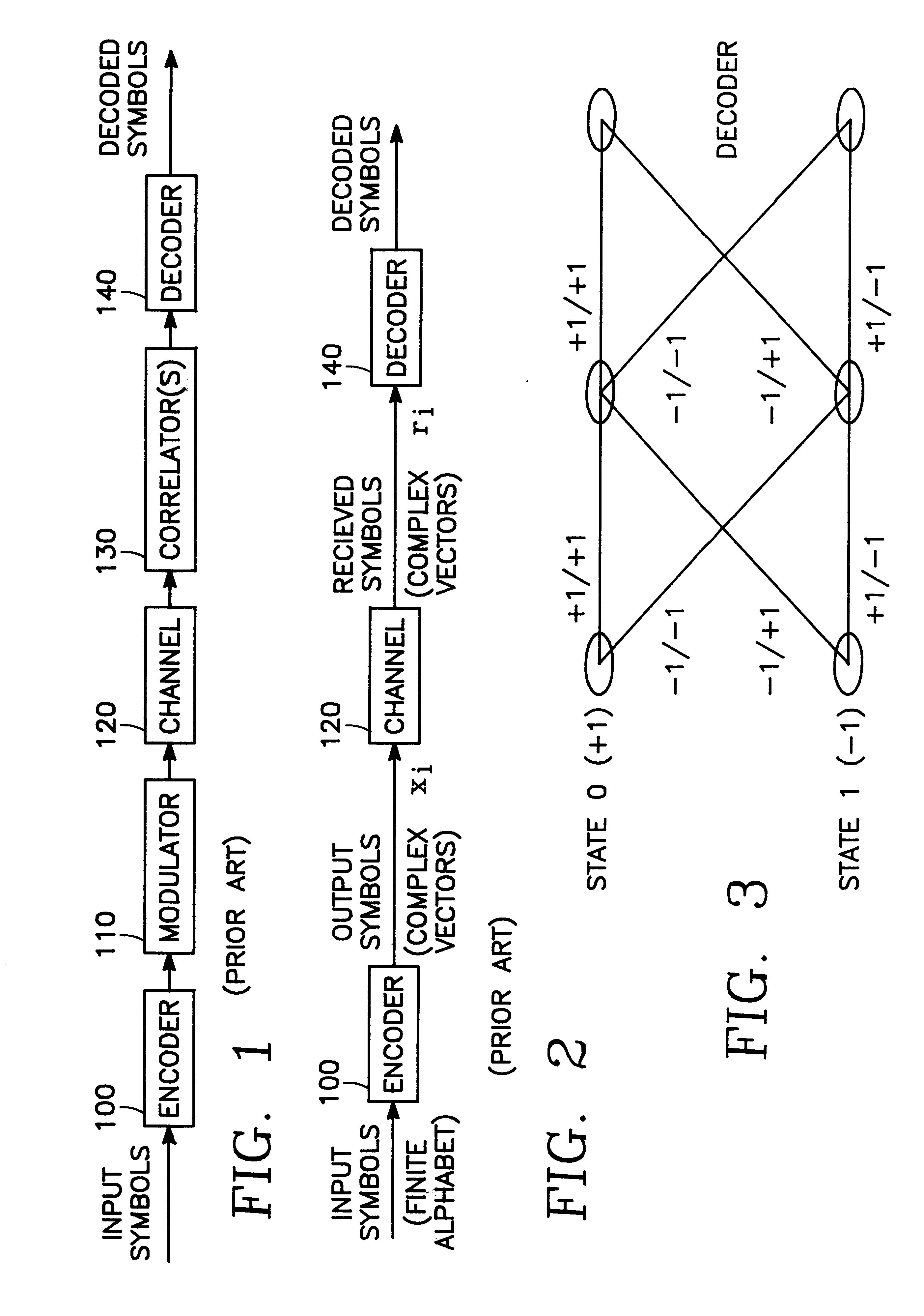
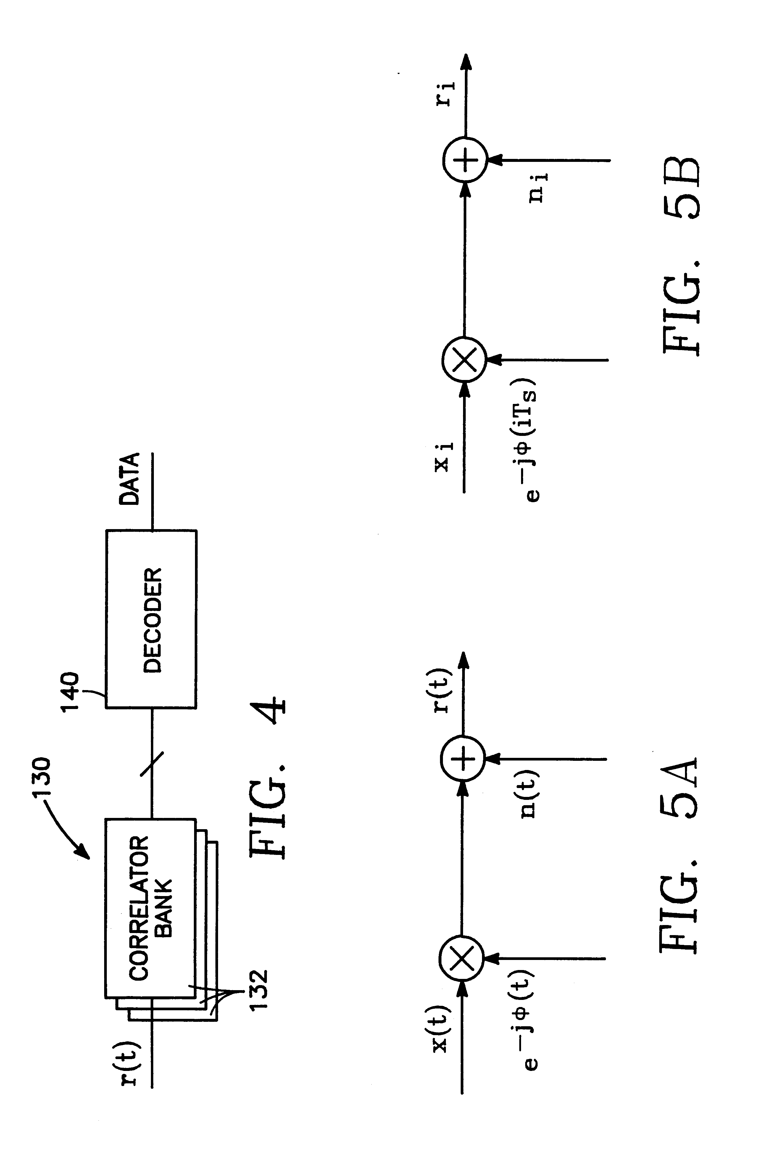
Referring to FIG. 23, we would like to decode a rate 1 / 2, K=3 code with BPSK modulation, and we choose L=3. The input to the decoder is as shown, where the numbers are real for simplicity. The symbols are in general complex vectors.

Initial conditions: 0 is received for t<0 and the state of the encoder is 0 at time t'-1, where all paths originate (it is not needed for the algorithm operation, only for the example). For t<2 we only compute the metrics--there are no decisions. At t=0:

F.sub.0.sup.0 ={0,0,0,0},

H.sub.0.sup.0 =(-0.5-1.5).sup.2 +(-0.5-1.5+0.5+0.8).sup.2 +(-0.5-1.5+0.5+0.8-0.9-0.9).sup.2 =10.74,

F.sub.0.sup.1 ={0,1,2,0},

H.sub.0.sup.1 =(0.5+1.5).sup.2 +(0.5+1.5-0.5+0.8).sup.2 +(0.5+1.5-0.5+0.8+0.9+0.9).sup.2 =26.1,

C.sub.0.sup.0 ={0,0}, G.sub.0.sup.0 =(-0.5-1.5).sup.2 =4,

C.sub.0.sup.1 ={0,1}, G.sub.0.sup.1 =4.

Step 1,2: s=0.fwdarw.m=0 and s=1.fwdarw.m=2.

F.sub.1.sup.0,0 ={0,0,0,0,0}, H.sub.1.sup.0,0 =10.74+(0.5+0.8-0.9-0.9-1-1).sup.2 =16.99,

F.sub.1.sup.1,2 ={0,1,2,0,0}, H.sub.1.s...


PUM


Abstract

In a communication system receiving from a channel a received signal corresponding to a succession of received symbols during a corresponding succession of symbol times, the succession of symbols corresponding to a succession states of a code of the communication system, each of the states branching to a predetermined number of others of the states, the invention provides a process for deducing an estimate of the succession of symbols from the received signal by overlapped observations of the received signal.

Description

1. Technical FieldThe present invention relates to modulation and demodulation of trellis modulated codes and in particular to processes for performing noncoherent coded modulation of such codes.2. Background ArtDigital communication systems used in practical applications are often very complicated. For example, the receiver for the NASA Deep Space Network took over one decade to develop and cost millions of dollars. Moreover, every communication system is different. There are many elements to be defined including the code, the modulation, the equalizer, the transmitted frequency, etc. For any such element, there are many possible methods of implementations. To investigate the theory of the operation of a digital communication system, it would be desirable to develop a unifying representation. Working in such a framework will enable us to treat a large class of communication systems as one.A baseband equivalent block diagram of a digital communication system is shown in FIG. 1. All ...

Claims


Application Information

Patent Timeline
Patent Type & Authority Patents(United States)
IPC IPC(8): H03M13/39H03M13/00H04L27/34H04L1/00
CPCH03M13/39H04L1/0054H04L1/006H04L27/3416
Inventor RAPHAELI, DAN
Owner CALIFORNIA INST OF TECH
Why Eureka
Try Eureka