
Active tremor control

a tremor and active technology, applied in the direction of shock absorbers, mechanical instruments, dampers with inertia effect, etc., can solve the problems of tremors that can adversely affect task performance, tidal toll, and miss the mark, and achieve the effect of light weigh

Inactive Publication Date: 2001-05-22
CHARLES STARK DRAPER LABORATORY
View PDF5 Cites 67 Cited by
  • Summary
  • Abstract
  • Description
  • Claims
  • Application Information

AI Technical Summary

Benefits of technology

It is therefore an object of this invention to provide an active tremor control system which is light weight and compact.
It is a further object of the present invention to provide such a tremor control system which may be easily and efficiently transported by the operator.
It is a further object of the present invention to provide such a tremor control system which stabilizes the device by counteracting only the tremor encountered by the device.
It is a further object of the present invention to provide such a tremor control system which is easily adaptable to different applications.

Problems solved by technology

Tremor can detrimentally affect task performance for a number of different tasks including microsurgery, marksmanship, photography, videotaping and microcircuit assembly as well as the simple use of a pen by a person afflicted with mild Parkinson's disease.
As an example, surgeons are often required to perform surgery on patients in areas which are very delicate and leave little or no room for error.
A surgeon performing surgery on the eye by cutting the eye with a laser or a scalpel must be very accurate, as a cut which is too deep, or in the wrong position, due to tremor of the surgeon's hand, can be disastrous.
However, human tremor resulting from the stress and excitement of the situation as well as the physical fatigue resulting from supporting the weapon for extended periods of time while waiting for the opportunity to make a shot can take its toll on a shooter so that when the time arrives to make the shot, the shot misses its mark.
A missed opportunity, whether missing the target completely or merely wounding the target, can further endanger the lives of others.
However, this takes the "trigger" away from the shooter, and thus the weapon may fire too early or too late.
Moreover, this technique does not solve the problem, but only masks it.
This system, however, only compensates for the jitter of the binoculars and does not counter or eliminate the jitter induced by the person holding the binoculars.
This system however, would not be practical for a surgeon or a sniper.
First, the gyroscopic wheel required would be too big compared to the rifle or the scalpel.
Second, this type of system resists all movement, especially rapid movement which is necessarily what a surgeon or sniper may encounter, such as when the surgeon moves the scalpel across the patient, or the sniper moves to acquire a second target or follows a primary target.
However, this system requires an inverter or 400 cycle power access to run the device.
This system is thus hardly practical when the application is a sniper who must make quick and often optimistic shots.
Moreover, because the system operates at a constant 22,000 revolution's per minute to resist any movement, it does not allow for rapid movement of the system which would be required by a sniper when the sniper must track a target or quickly acquire a second target.
However, there are systems which do not have such a platform to push against.
However, that system only provides for the proper attitude of the satellite antenna with respect to a receiving station on earth and does not eliminate jitter of the satellite in response to any external disturbances.

Method used


Image

  • Active tremor control
  • Active tremor control
  • Active tremor control

Examples


Embodiment Construction

Other objects, features and advantages will occur to those skilled in the art from the following description of a preferred embodiment and the accompanying drawings, in which:

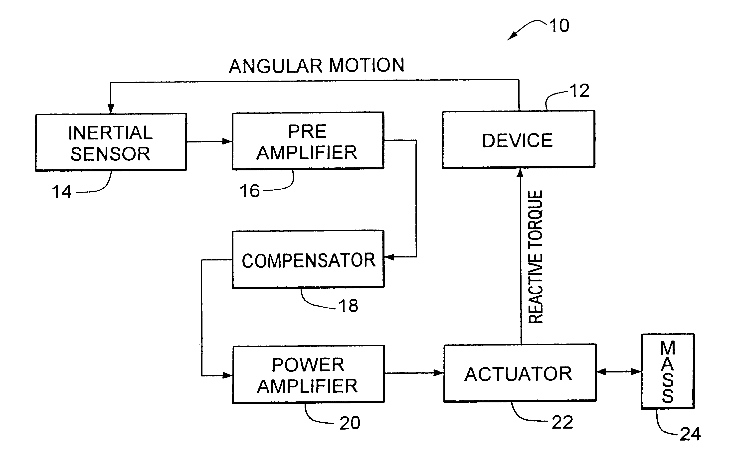
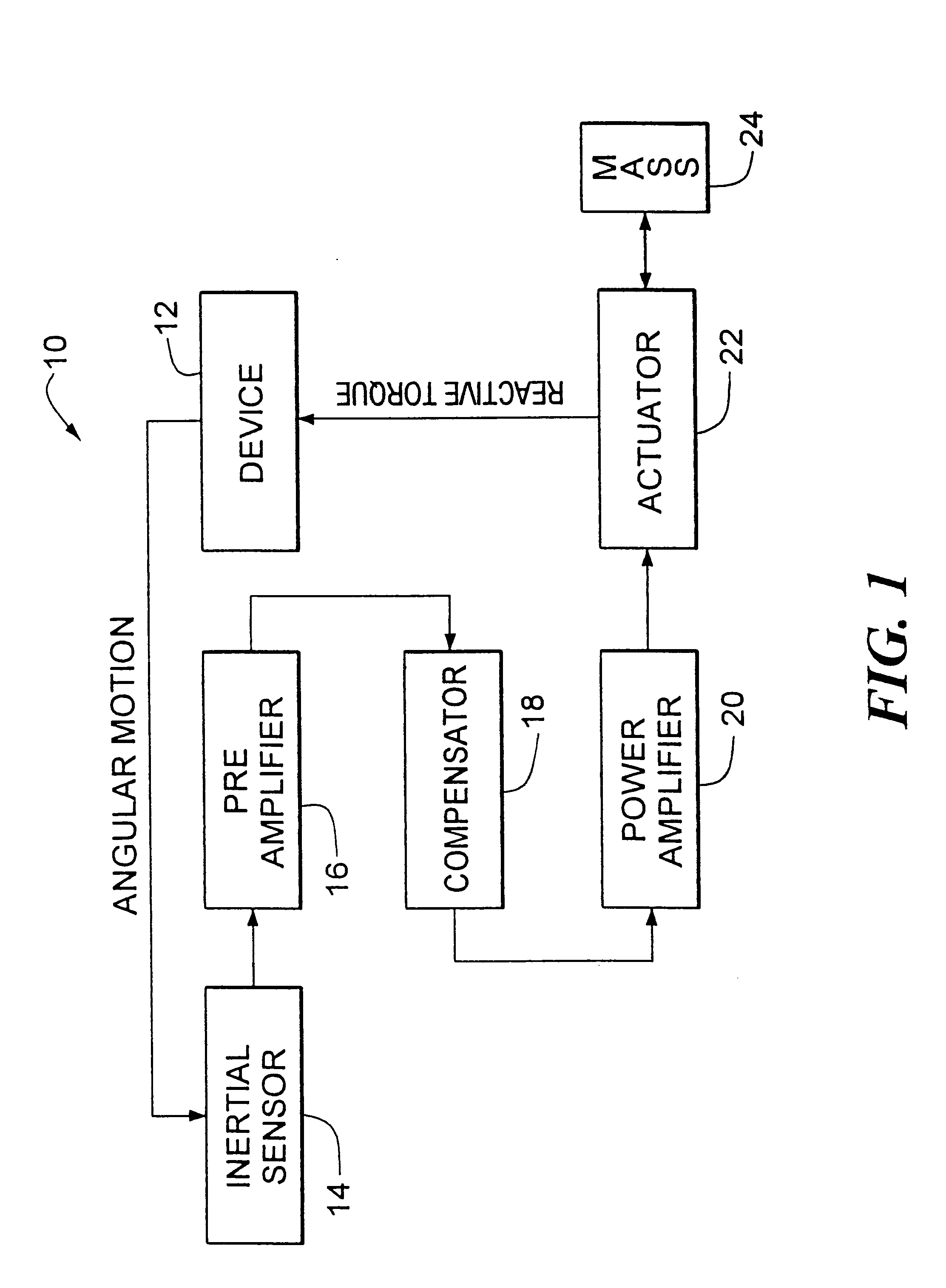
FIG. 1 is a block diagram of the closed loop tremor control system according to the present invention,

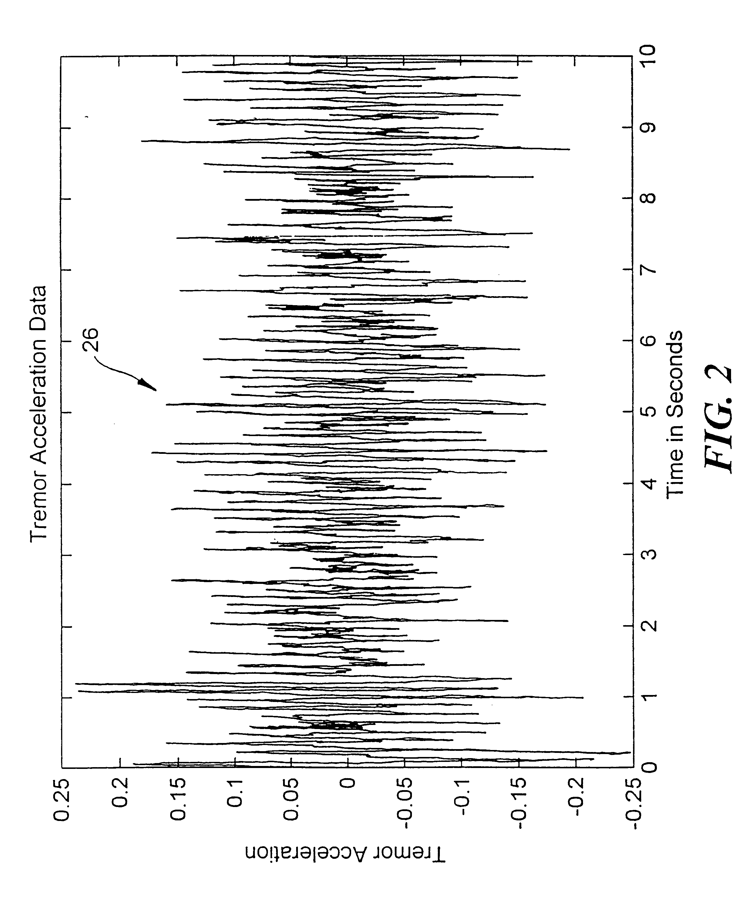
FIG. 2 is a representation of the tremor associated with a human finger under no load;

FIG. 3 is a representation of the spectral density of the tremor of FIG. 2;

FIG. 4 is a schematic block diagram of the tremor control system according the present invention applied to a firearm demonstrating how a motor applies a torque to the firearm, equal and opposite to the tremor sensed, and simultaneously applies a reactive torque to a mass to cancel the sensed tremor;

FIG. 5 is a three-dimensional view of the tremor control system of the present invention mounted on a rifle in which an inertial sensor senses pitch and an inertial wheel cancels the pitch while another inertial sensor senses yaw and an inertial wheel cancel...


PUM


Abstract

An active tremor control system for stabilizing against alternating perturbations includes: an inertial sensor for sensing angular motion about a first axis of an object induced by alternating perturbations; an inertial mass independent of the object; and an actuator coupled to the object and the mass and responsive to the inertial sensor for selectively applying a torque to the object representative of the sensed angular motion such that the angular motion about the first axis induced by the perturbation is cancelled, the actuator concurrently applying a reactive torque, equal and opposite to the to the applied torque, to the mass.

Description

This invention relates to stabilization systems, and more particularly to a tremor control system for stabilizing an object from prolonged alternating perturbations.BACKGROUND OF INVENTIONHuman tremor is an involuntary trembling or shaking of the muscles of the body associated with physical weakness, emotional stress, or excitement. Tremor can detrimentally affect task performance for a number of different tasks including microsurgery, marksmanship, photography, videotaping and microcircuit assembly as well as the simple use of a pen by a person afflicted with mild Parkinson's disease.As an example, surgeons are often required to perform surgery on patients in areas which are very delicate and leave little or no room for error. One such example is eye surgery. A surgeon performing surgery on the eye by cutting the eye with a laser or a scalpel must be very accurate, as a cut which is too deep, or in the wrong position, due to tremor of the surgeon's hand, can be disastrous.Another e...

Claims


Application Information

Patent Timeline
IPC IPC(8): F16F7/10
CPCF16F7/1005Y10T74/2121F41G3/12
Inventor KAISER, KENNETH W.
Owner CHARLES STARK DRAPER LABORATORY
Learn More