Organic electroluminescent device

a technology of electroluminescent devices and organic el, which is applied in the direction of discharge tube luminescnet screens, natural mineral layered products, etc., can solve the problems of inability to maintain consistent light emission, acutely sensitive to moisture, and non-light emission spots called dark spots

Inactive Publication Date: 2001-07-31
FUTABA CORPORATION
View PDF7 Cites 103 Cited by
  • Summary
  • Abstract
  • Description
  • Claims
  • Application Information

AI Technical Summary

Benefits of technology

The present invention has for its object to provide an organic EL device which, in terms of deterioration with time, is reduced as much as possible so as to have an ever longer service life, so that its initial performance can be maintained over a long period of time.

Problems solved by technology

A grave problem with an organic EL device is that it is acutely sensitive to moisture.
This results in another problem that non-light emission spots called dark spots occur or any consistent light emission cannot be kept.
Even with the provision of such a sealing layer, however, several problems still arise; as driving time goes by, the light emission luminance decreases or the dark spots occur.
If the dark spots become large, then the device will deteriorate and, in the worst case, the device will be unable to work.

Method used


Image

  • Organic electroluminescent device
  • Organic electroluminescent device

Examples


experiment 1

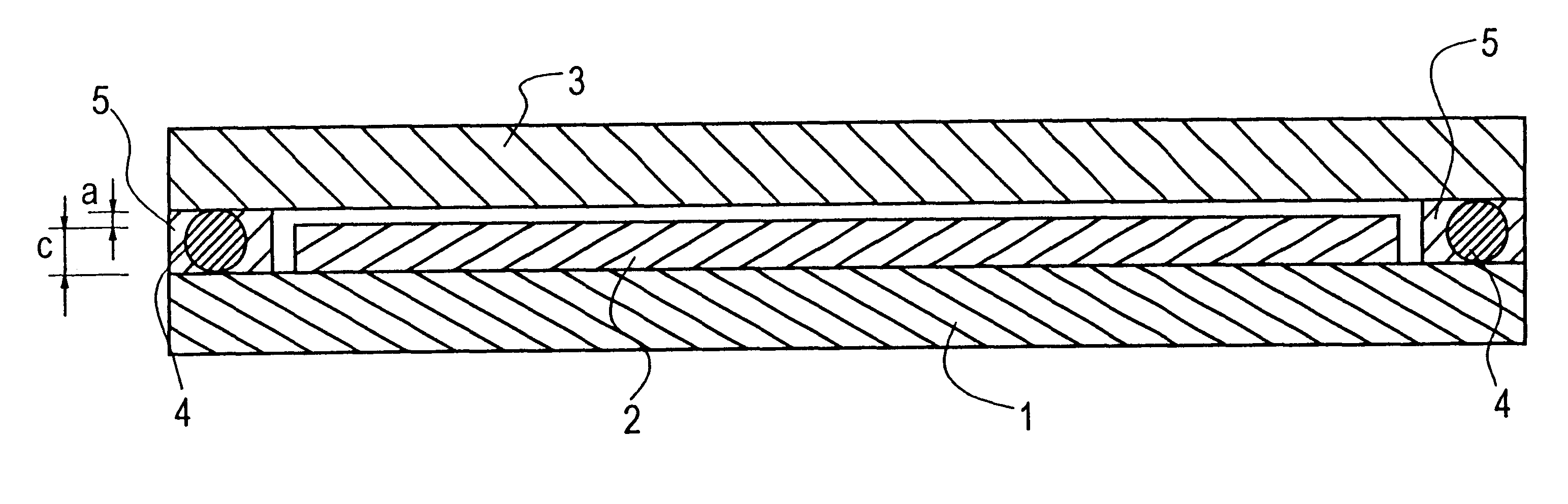
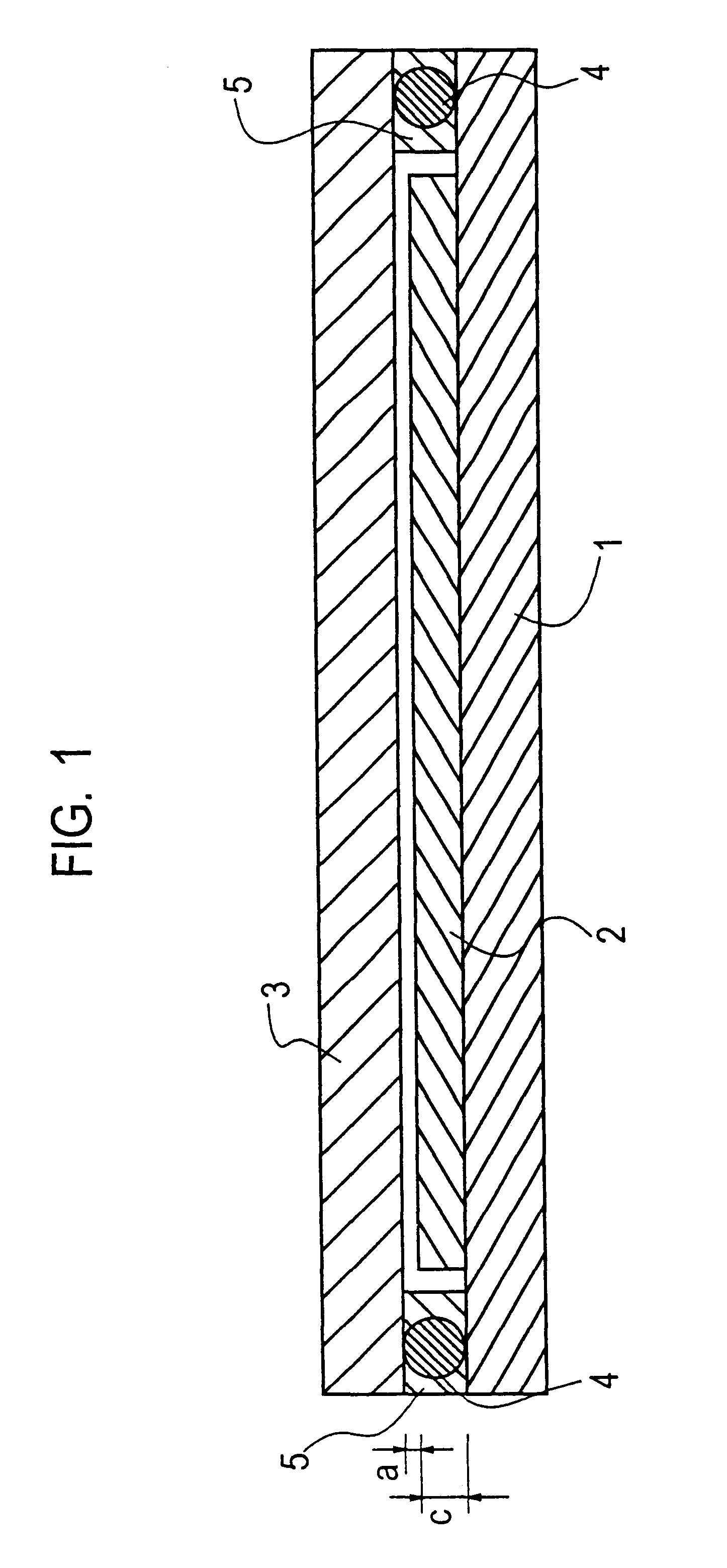
A commercially available ultraviolet curing type epoxy resin adhesive agent 30Y296D (100 mg, made by Three Bond) in an uncured state was coated on a substrate of glass 7059 (made by Corning). Another glass 7059 (Corning) serving as a sealing plate was put over the substrate. Then, they were pressurized at a pressure of 3 kg / cm.sup.2 while they were ground together, thereby forming a thin adhesive agent layer between the glass substrate and the glass sealing plate. At this time, 7 .mu.m spacers (1 wt %) were dispersed in the adhesive agent to obtain an adhesive agent layer of 7 .mu.m in thickness. Then, the adhesive agent surface was irradiated through the glass substrate with ultraviolet light from a metal halide lamp and in an integral light quantity of 600 mJ, thereby curing the adhesive agent. After curing, the sealing plate was peeled off the glass substrate to expose the bonded surface to view, from which the adhesive agent (about 50 mg) was scratched off. The thus obtained sam...

experiment 2

A sample was analyzed as in Experiment 1 with the exception that an adhesive agent containing a metallocene compound as a reaction initiator was used for a comparative adhesive agent sample. As a result, the total amount of gases generated from the comparative adhesive agent sample after ultraviolet curing was a very large value of 217 .mu.g / g.

example 1

An organic EL device was prepared using the inventive sample employed in Experiment 1.

A glass substrate was provided thereon with an 85 nm-thick ITO transparent electrode (hole injecting electrode) in such a way that pixels (280.times.280 .mu.m per pixel) were patterned on the ITO transparent electrode according to an array of 64 dots.times.7 lines. Then, the substrate with the patterned hole injecting electrode formed on it was ultrasonically washed with neutral detergent, acetone, and ethanol, and then pulled up from boiling ethanol, followed by drying. The substrate was subsequently cleaned on its surface with UV / O.sub.3. Then, the substrate was fixed to a substrate holder in a vacuum evaporation system, which was evacuated to a vacuum of 1.times.10.sup.-4 Pa or lower. 4,4',4"-tris(-N-(3-methylphenyl)-N-phenylamino)triphenylamine (m-MTDATA) was deposited by evaporation at a deposition rate of 0.2 nm / sec. to a thickness of 40 nm, thereby forming a hole injecting layer. With the va...


PUM

PropertyMeasurementUnit
voltageaaaaaaaaaa
temperatureaaaaaaaaaa
glass transition temperatureaaaaaaaaaa

Abstract

An organic EL device comprises a substrate, an organic EL structure stacked on the substrate, a sealing plate located on the organic EL structure with a predetermined space therebetween, and a sealing adhesive agent for fixing the sealing plate on the substrate and thereby closing up the organic EL structure. The sealing adhesive agent is a photo-curing type adhesive agent which, upon photo-curing, generates gases under heating conditions of 85° C. and 60 minutes. In these gases, the total amount of a low-molecular straight-chain aliphatic hydrocarbon which may have a substituent, an aromatic hydrocarbon which may have a substituent, an alicyclic hydrocarbon which may have a substituent, and a heterocyclic compound and a siloxane which may have a substituent is 200 mug / g or lower calculated as benzene. The organic EL device of the invention is reduced as much as possible in terms of a deterioration with time, and can maintain its initial performance over a long period of time, so that it can have an ever longer service life.

Description

The present invention relates generally to an organic EL (electroluminescent) device using an organic compound, and more specifically to an improvement in or relating to an adhesive agent for fixing a sealing plate in place to protect an organic EL structure stacked on a substrate.In recent years, organic EL devices have been under intensive investigation. One such device is basically built up of a thin film form of hole transporting material such as triphenyldiamine (TPD) deposited by evaporation on a hole injecting electrode, a light emitting layer of fluorescent material such as an aluminum quinolinol complex (Alq.sup.3) laminated thereon, and a metal (electron injecting) electrode of a metal having a low work function such as Mg and formed on the light emitting layer. This organic EL device now attracts attentions because a very high luminance ranging from several hundreds to tens of thousands cd / m.sup.2 can be achieved with a voltage of approximately 10 V.A grave problem with a...

Claims


Application Information

Patent Timeline
Patent Type & Authority Patents(United States)
IPC IPC(8): H01L51/52H01L51/50H05B33/04
CPCH01L51/5237H05B33/04Y10S428/917Y10S428/913H10K50/8428H10K50/8426
Inventor YASUKAWA, KOUJIENDO, HIROYUKIKATO, HIDEOSHIMAMURA, JUNICHIONITSUKA, OSAMUEBISAWA, AKIRA
Owner FUTABA CORPORATION
Why Eureka
Try Eureka