Closed electron drift plasma thruster adapted to high thermal loads

a plasma thruster and closed electron technology, applied in the direction of ion beam tubes, machines/engines, magnetic discharge control, etc., can solve the problems of high temperature of a large plasma thruster of known type, inability to optimize the evacuation of heat flux, and inability to have a power level of closed electron drift plasma thrusters, etc., to achieve the effect of optimizing operation and heat flux evacuation and greater power

Inactive Publication Date: 2001-08-28
SN DETUDE & DE CONSTR DE MOTEURS DAVIATION S N E C M A
View PDF6 Cites 29 Cited by
  • Summary
  • Abstract
  • Description
  • Claims
  • Application Information

AI Technical Summary

Benefits of technology

The invention seeks to remedy the above-specified drawbacks and to make it possible to optimize operation and heat flux evacuation in closed electron ...

Problems solved by technology

The structural characteristics of presently known closed electron drift plasma thrusters do not make it possible to optimize evacuation of the heat flux in operation.
As a result, closed electron drift plasma thrusters cannot have a power level that is high enough to provide the primary propulsion of a mission such as transferring to geos...

Method used


Image

  • Closed electron drift plasma thruster adapted to high thermal loads
  • Closed electron drift plasma thruster adapted to high thermal loads
  • Closed electron drift plasma thruster adapted to high thermal loads

Examples


Embodiment Construction

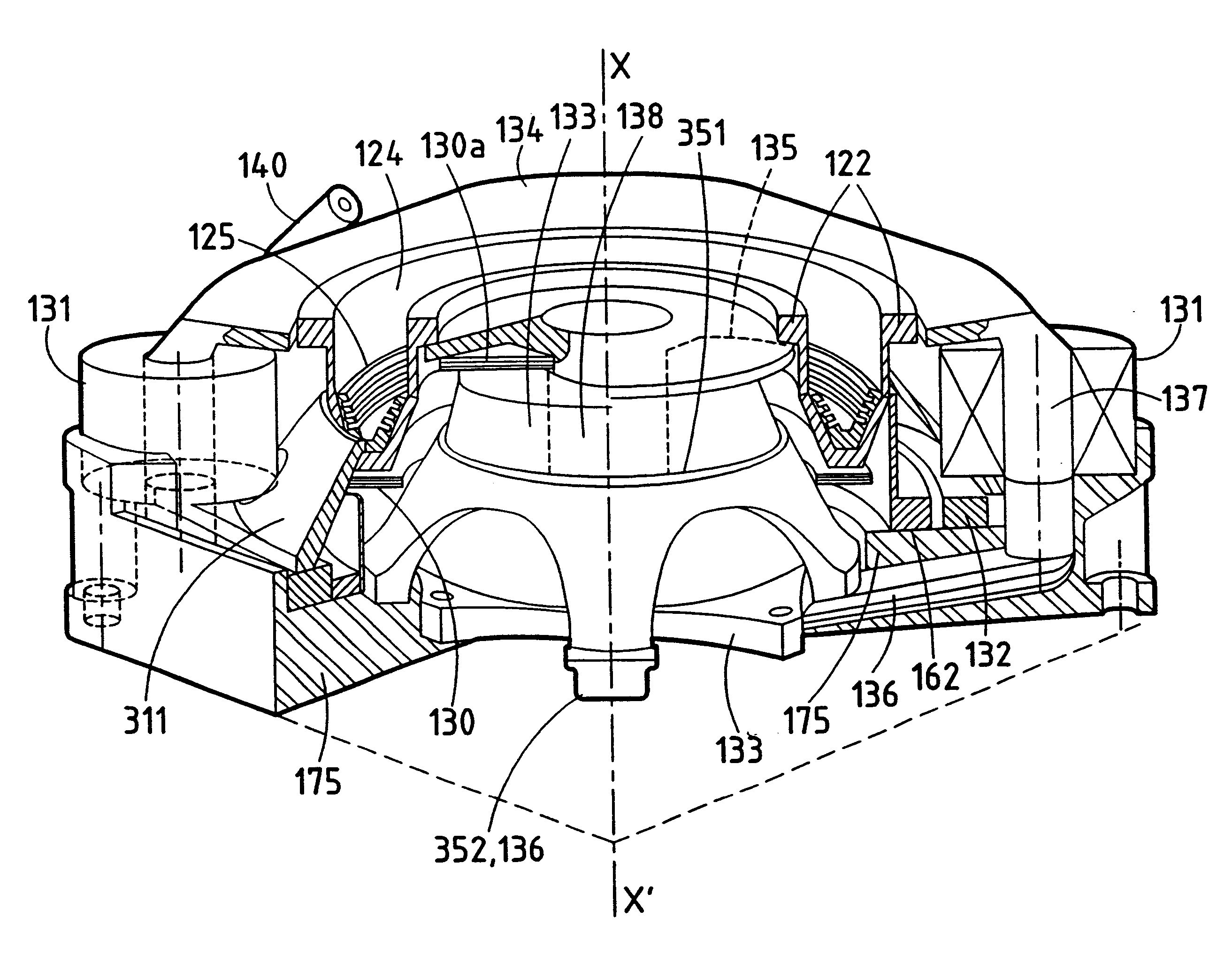
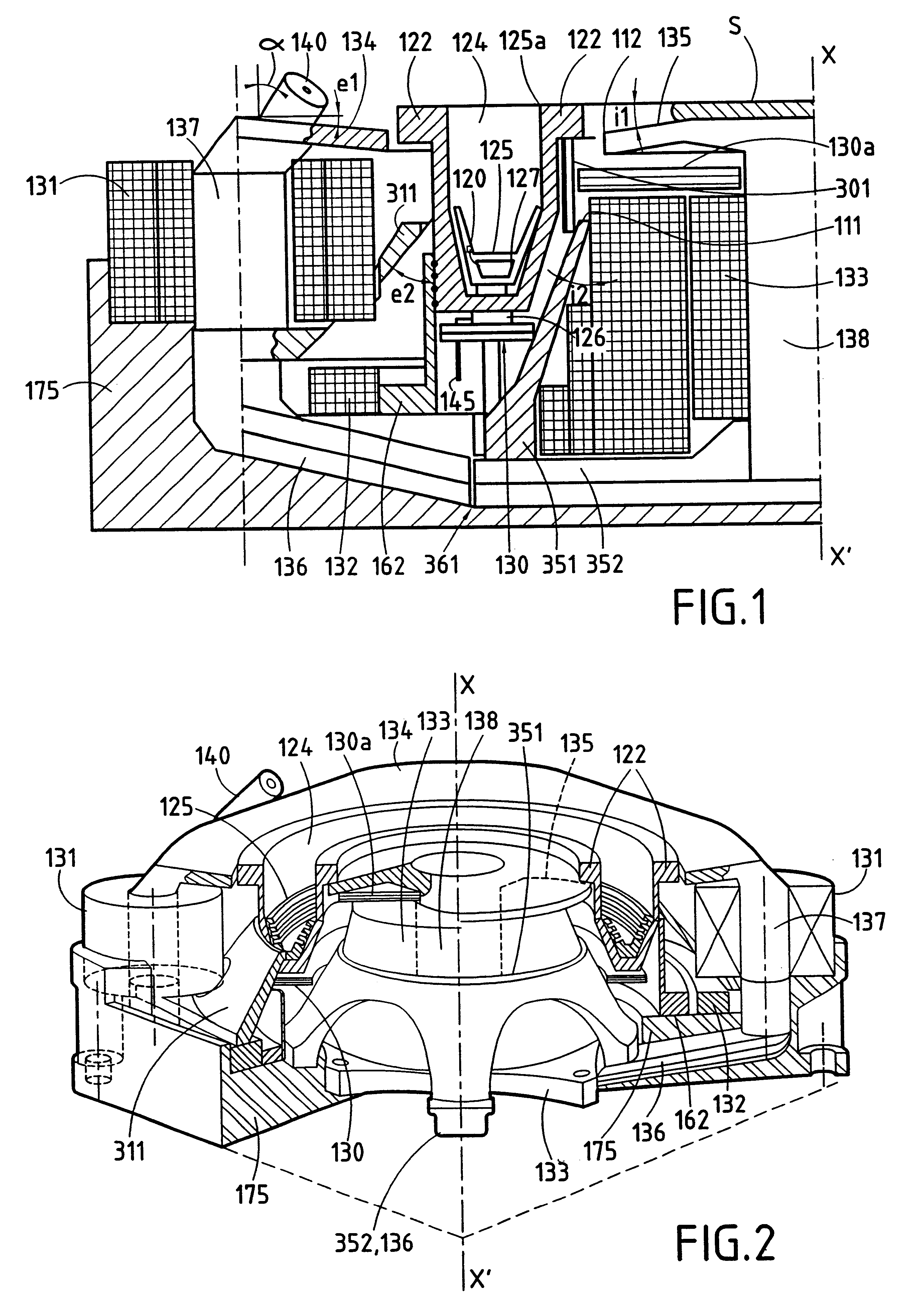
Reference is made initially to FIGS. 1 and 2 showing a first example of a closed electron drift plasma thruster of the present invention.

The closed electron drift plasma thruster of FIGS. 1 and 2 comprises a main annular channel 124 for ionization and acceleration which is defined by insulating walls 122. The channel 124 is open at its downstream end 125a and in an axial plane its section is frustoconical in shape in its upstream portion and cylindrical in its downstream portion.

A hollow cathode 140 is disposed outside the main channel 124 and is advantageously at an angle .alpha. relative to the axis X'X of the thruster, where a lies in the range 15.degree. to 45.degree..

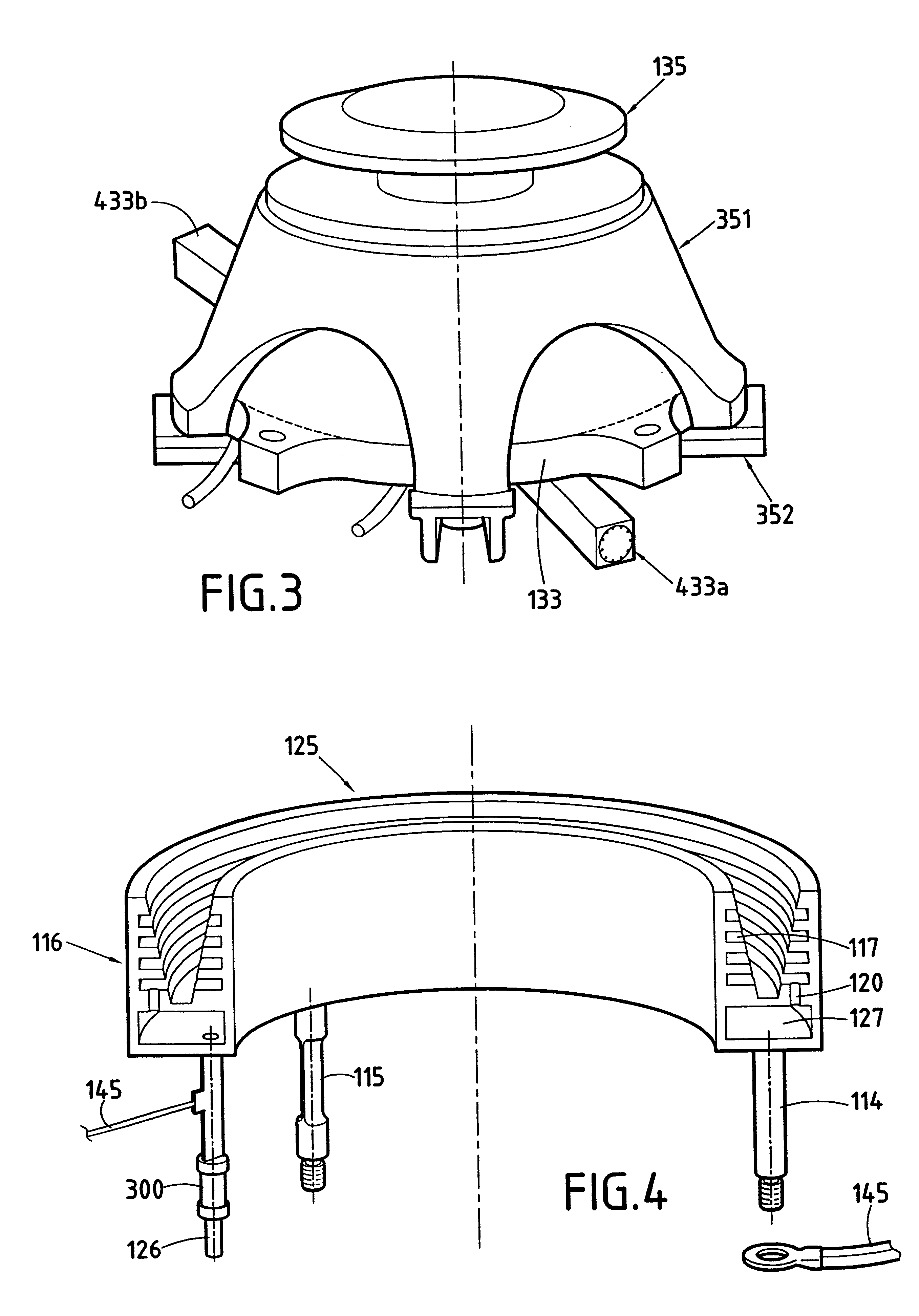
In an axial plane, an annular anode 125 has a tapering section in the form of a truncated cone that is open in a downstream direction.

The anode 125 can have slots increasing its surface area in contact with the plasma. Holes 120 for injecting an ionizable gas coming from an ionizable gas distribution manifold 127 a...


PUM


Abstract

The closed electron drift plasma thruster uses a magnetic circuit to create a magnetic field in a main annular channel for ionization and acceleration, said magnetic circuit comprises: an essentially radial first outer pole piece; a conical second outer pole piece; an essentially radial first inner pole piece; a conical second inner pole piece; a plurality of outer magnetic cores surrounded by outer coils to interconnect the first and second outer pole pieces; an axial magnetic core surrounded by a first inner coil and connected to the first inner pole piece; and a second inner coil placed upstream from the outer coils. The thruster also comprises a plurality of radial arms included in the magnetic circuit, and a structural base which is separate from the magnetic circuit and which serves, amongst other things, to cool the coils.

Description

The present invention relates to a closed electron drift plasma thruster adapted to high thermal loads, the thruster comprising a main annular channel for ionization and acceleration that is defined by parts made of insulating material and that is open at its downstream end, at least one hollow cathode disposed outside the main annular channel adjacent to the downstream portion thereof, an annular anode concentric with the main annular channel and disposed at a distance from the open downstream end, a pipe and a distribution manifold for feeding the annular anode with an ionizable gas, and a magnetic circuit for creating a magnetic field in the main annular channel.PRIOR ARTClosed electron drift plasma thrusters having the structure shown in section in FIG. 13 are already known, e.g. from document EP-A-0 541 309.A thruster of that type comprises a cathode 2, an anode-forming gas distribution manifold 1, an annular acceleration channel (discharge chamber) 3 defined by inner and outer...

Claims


Application Information

Patent Timeline
IPC IPC(8): F03H1/00H05H1/00H05H1/54
CPCF03H1/0031H05H1/54F03H1/0075
Inventor VALENTIAN, DOMINIQUEBUGEAT, JEAN-PIERREKLINGER, ERIC
Owner SN DETUDE & DE CONSTR DE MOTEURS DAVIATION S N E C M A
Why Eureka
Try Eureka