Method and apparatus for span and subspan sorting rendering system

a sorting and subspan technology, applied in the field of three-dimensional computer graphics, can solve the problems of inability to build a cost-effective manner, the depth complexity of a scene is a measure of wasted processing, and the methods more complicated than the z-buffer technique have heretofore generally been too complex to achieve the effect of simplifying downstream processing and increasing compatibility

Inactive Publication Date: 2001-09-04
APPLE INC
View PDF4 Cites 101 Cited by
  • Summary
  • Abstract
  • Description
  • Claims
  • Application Information

AI Technical Summary

Benefits of technology

The inventive apparatus, system, and method also provide several options and enhancements to the basic system. These include, by way of example: preservation of rendering order, utilization of a single-buffered frame buffer for increased compatibility with conventional video cards, the ability to selectively turn on or off antialiasing on specific polygon edges, the ability to store edge-pairs rather than polygons thereby simplifying downstream processing, the ability to eliminate the Current Polygon Memory by replacing it with a list of pointers, the ability to add clipping planes (front, rear, and / or arbitrary), provision of the Geometry Cache for storing geometry as it is input for rendering, flexible options for the number of pages of Span Memory and Page Memory I / O bus architecture, support for geometry primitives other than polygons (such as CSG primitives), and alternatives that support the inventive method in conventional hardware with some performance compromises.

Problems solved by technology

As scene models become more and more complicated, renderers will be required to process scenes of ever increasing depth complexity.
Thus, for most renders, the depth complexity of a scene is a measure of the wasted processing.
Methods more complicated that the Z-buffer technique have heretofore generally been too complex to build in a cost-effective manner.
A major drawback to the generic 3D graphics pipeline 200 is its drawing intensive functions 260 are not deterministic at the pixel level given a fixed number of polygons.
Therefore, it is difficult to balance the amount of computational power between the floating-point intensive functions 250 and the drawing intensive functions 260 because this balance depends on the average polygon size.
The drawback with using subpixels is the increase in computation due to computing color values at every subpixel.
The main drawback to this technique is the need to sort polygons front-to-back (or back-to-front) at each pixel in order to get acceptable antialiased polygons.
The main drawback to the Z-buffer hidden surface removal method is the requirement for geometry to be converted to pixel values before hidden surface removal can be done.
For scenes with any significant depth complexity, pixel-by-pixel hidden surface removal introduces much wasted computation by requiring all geometry within the view volume to be converted to pixels, even though most are hidden and, therefore, thrown away.
Furthermore, the Z-buffer memory operation is a read-modify-write cycle, generally requiring the Z-buffer memory input / output bus to change directions twice when writing pixels into the frame buffer, thereby causing a bottleneck in the renderer.
It is inefficient to perform magnitude comparisons in a equality-testing CAM because a large number of clock cycles is required to do the task.
CAMs are not used in any practical prior art renders.

Method used


Image

  • Method and apparatus for span and subspan sorting rendering system
  • Method and apparatus for span and subspan sorting rendering system
  • Method and apparatus for span and subspan sorting rendering system

Examples


Embodiment Construction

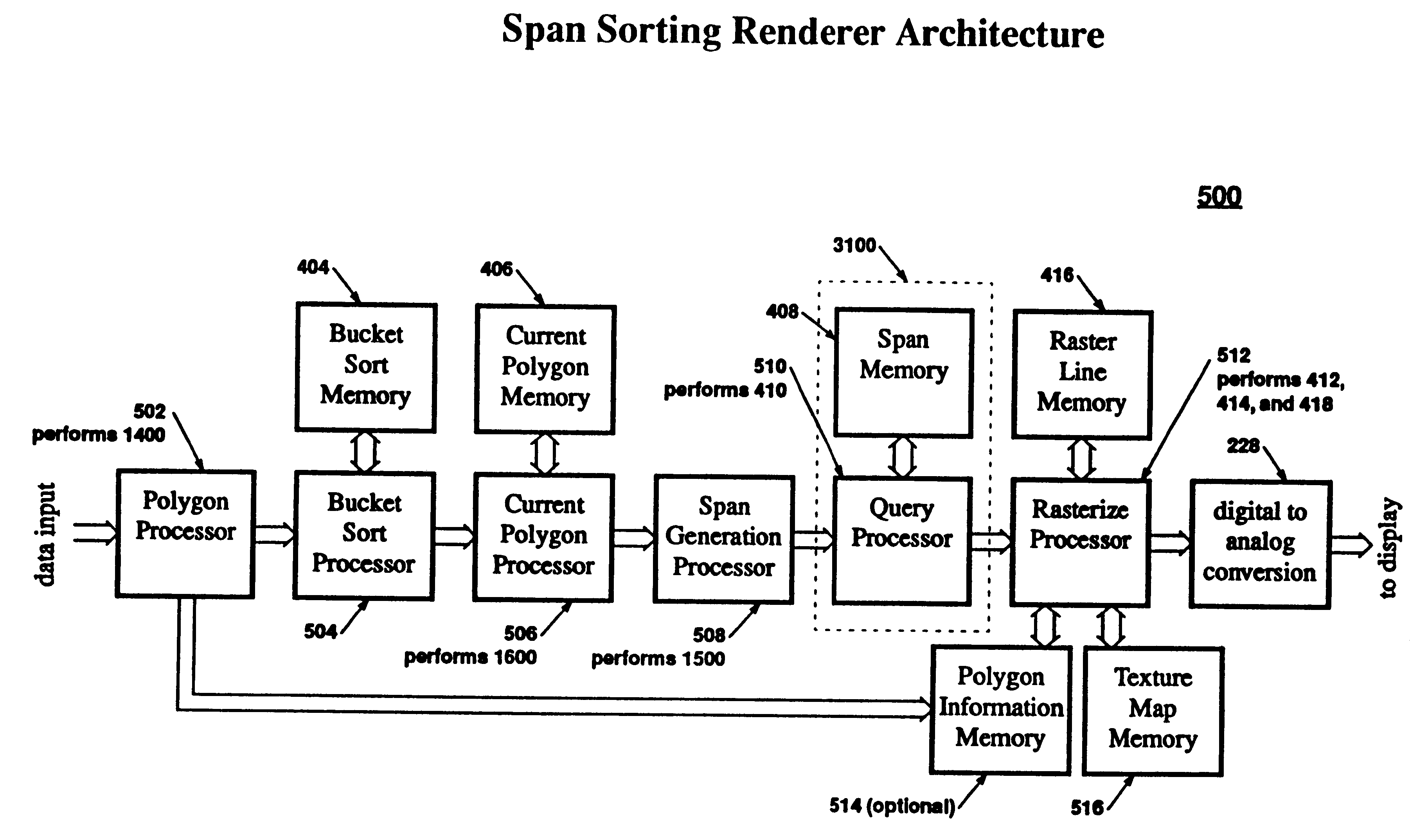
Span Sorting Rendering Pipeline

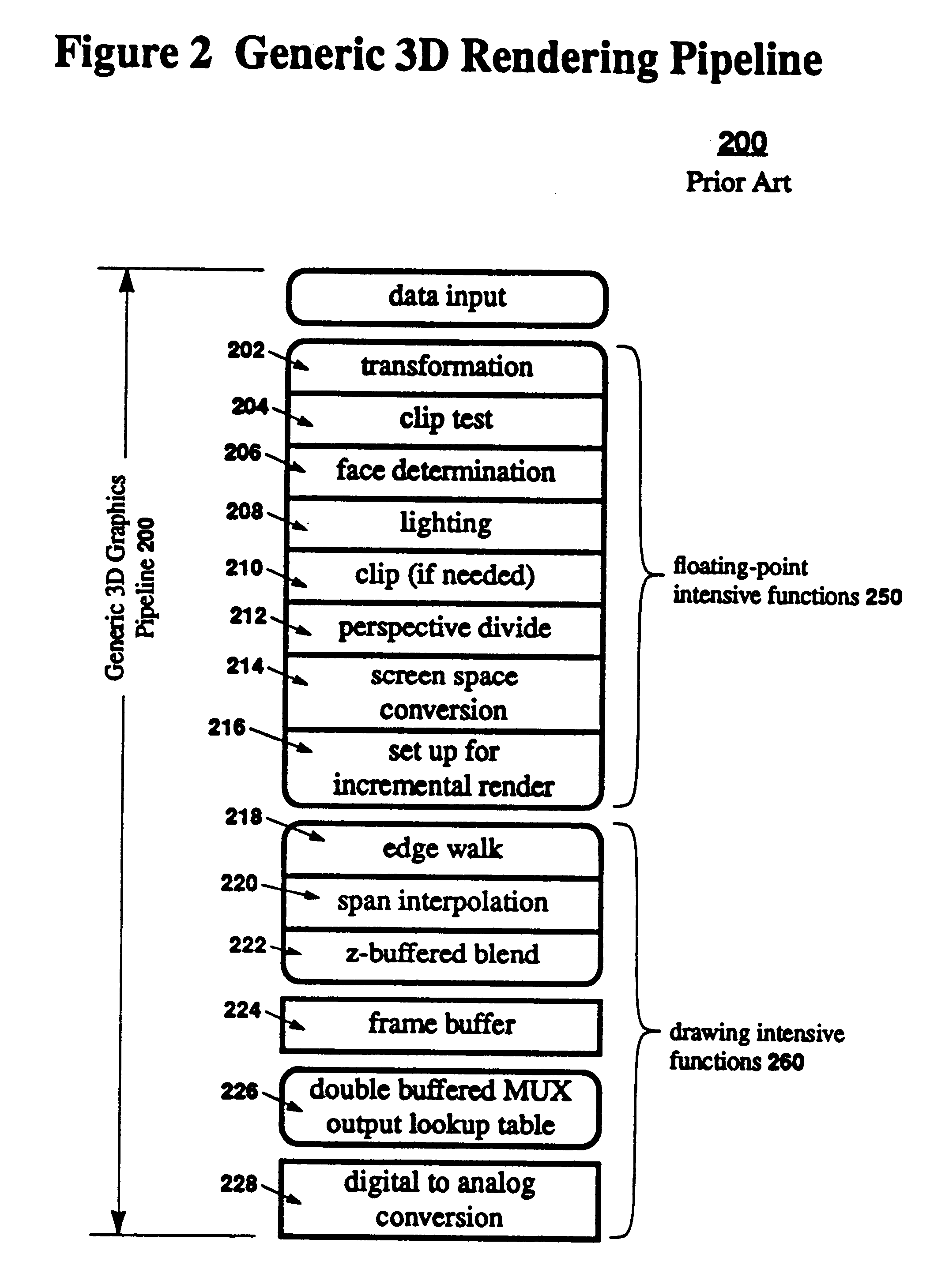
FIG. 4 shows the Span Sorting 3D Graphics Pipeline 400, where the first six steps are defined as the process polygon 1400 steps. The first five steps (transformation 202, clip test 204, face determination 206, lighting 208, and perspective divide 212) are the same as the five of the first six steps in the Generic 3D Graphics Pipeline 200. The clip 210 step is omitted because the Span Sorting 3D Graphics Pipeline 400 operates in object-precision, and coordinates are not limited to the area of the display screen 104. Elimination of the clip 210 step allows all polygons in the view volume 106 to be treated the same. However, the clip 210 step can be inserted if desired. The Span Sorting 3D Graphics Pipeline 400 can be built with dedicated hardware, done completely in software, or a combination of the two. Hereinafter, a dedicated hardware implementation is assumed, and a new apparatus is described.

The top-level block diagram of the new apparatus is shown ...


PUM


Abstract

A data shifting capability that permits sorting the data in addition to searching for obtaining real-time performance in color, with high quality imagery through a simple search of a spacial database based on a rectangularly shaped search region or range search. A sorting Magnitude Comparison Content Addressable Memory (SMCCAM) performs a range search, introducing a conservative approximation of the idea Occluding Region, and provides a MCCAM wherein the data words stored in the fields are shifted to corresponding fields in an adjacent word, based on the magnitude comparisons. The 3D graphics method stores the parameters of a polygon span in a spatial database and a query operation is performed on the database to determine which of those spans, or portions of spans, are visible, and applies a rule for comparing a new span portion to an old span portion on a subspan-by-subspan basis, thereby providing additional polygon edge information within a raster line, providing anti-aliasing.

Description

FIELD OF THE INVENTIONThe field of this invention is twofold: 1) three-dimensional computer graphics; and 2) computer memories, and more specifically, Content Addressable Memories (CAM).BACKGROUND OF THE INVENTIONThree-Dimensional Computer GraphicsComputer graphics is the art and science of generating pictures with a computer. Generation of pictures, or images is commonly called rendering. Generally, in three-dimensional (3D) computer graphics, geometry that represents surfaces (or volumes) of objects in a scene is translated into pixels stored in a frame buffer, and then displayed on a display device. Real-time display devices, such as CRTs used as computer monitors, refresh the display by continuously displaying the image over and over. This refresh usually occurs row-by-row, where each row is called a raster line or scan line. In this document, raster lines are numbered from bottom to top, but are displayed in order from top to bottom.In a 3D animation, a sequence of images is di...

Claims


Application Information

Patent Timeline
Patent Type & Authority Patents(United States)
IPC IPC(8): G06T15/10G06T15/00G06T11/40G09G5/36
CPCG06T15/10G06T15/005
Inventor DULUK, JR., JEROME F.
Owner APPLE INC
Why Eureka
Try Eureka