
Wastewater treatment tank with influent gates and pre-react zone with an outwardly flared lower portion

a technology of influent gates and pre-react zones, which is applied in the direction of sustainable biological treatment, biological water/sewage treatment, sedimentation settling tanks, etc., can solve the problems of many current wastewater treatment plants operating near, increasing the workload of facilities, and increasing the flow velocity of influents

Inactive Publication Date: 2001-10-16
LINDBO GLEN D
View PDF40 Cites 64 Cited by
  • Summary
  • Abstract
  • Description
  • Claims
  • Application Information

AI Technical Summary

Benefits of technology

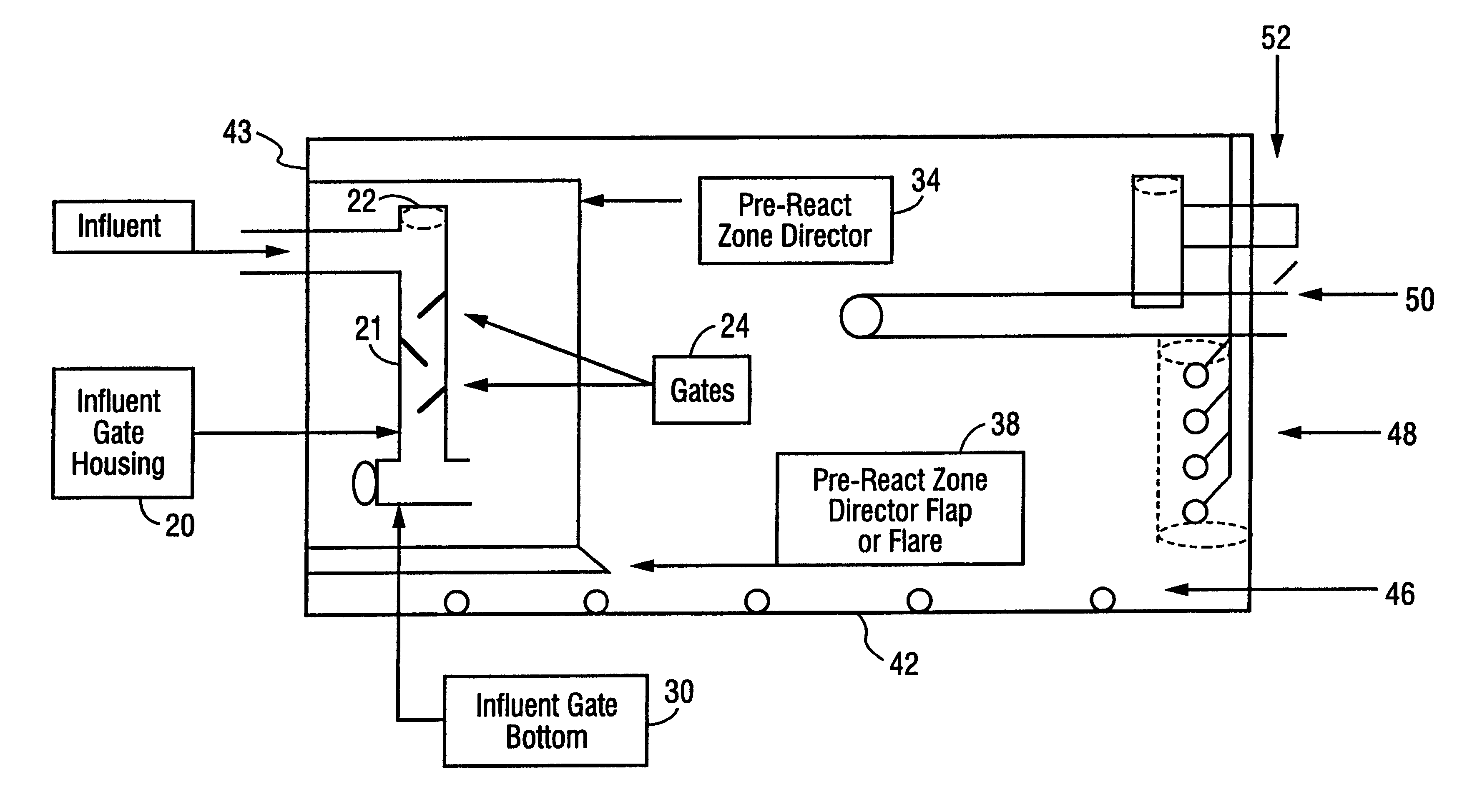
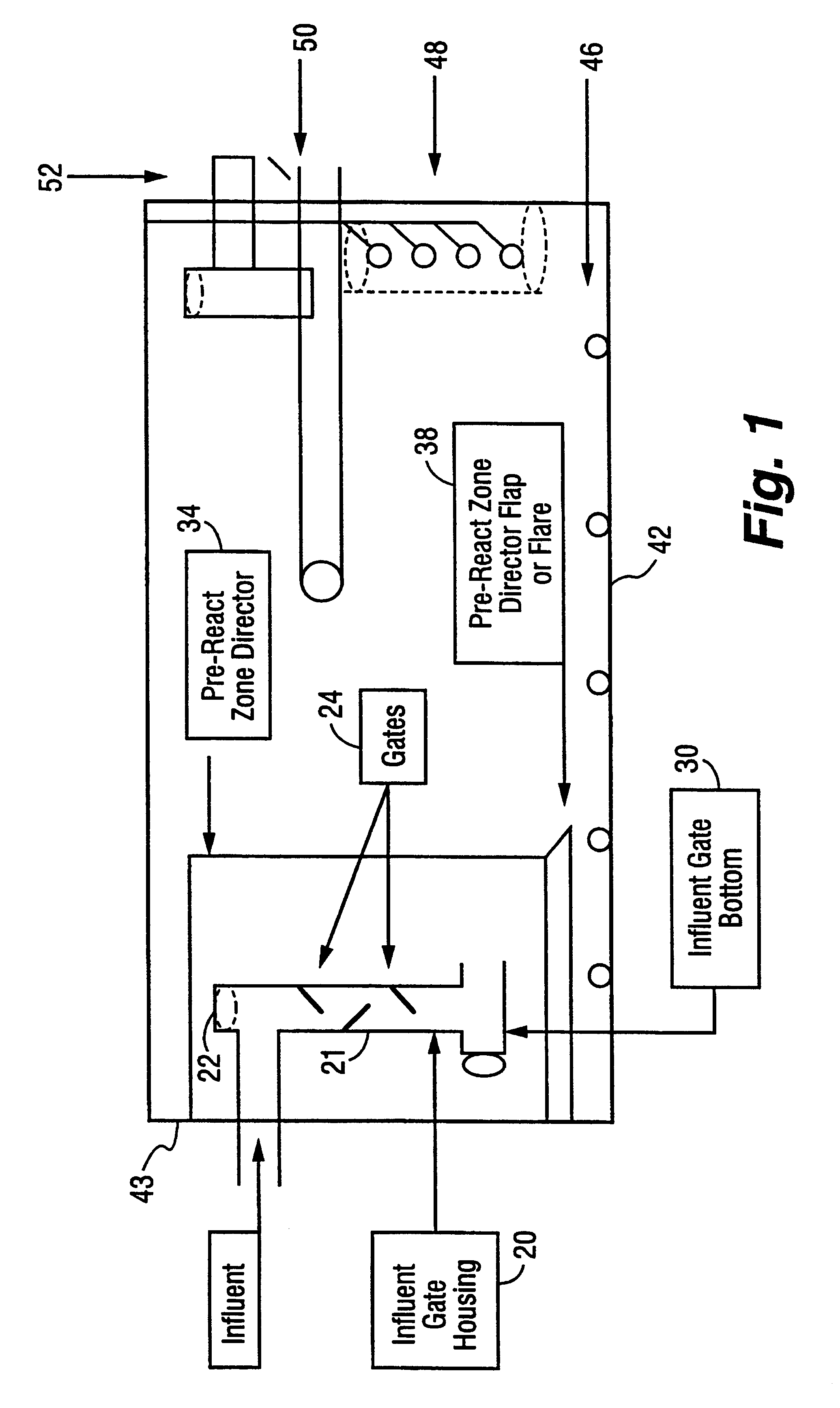
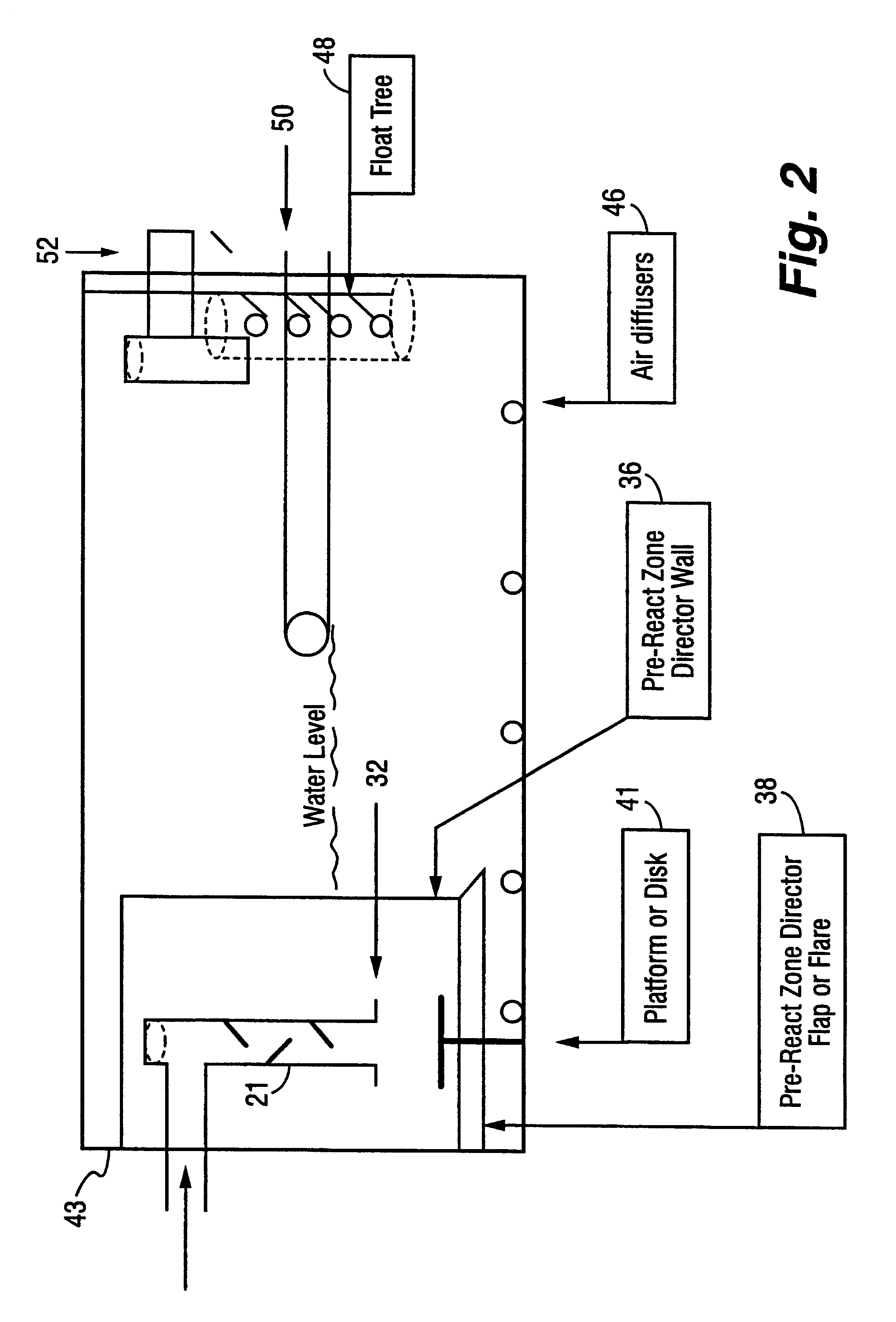
These and other objects are achieved by a device to treat influent that includes a basin with an influent gate housing in the basin to receive influent. Influent gates are mounted inside the influent gate housing so that influent flows over the influent gates, creating turbulent flow and aeration in the influent, and reducing flow velocity of the influent. An influent gate bottom is mounted in the basin under the influent gate housing so that influent exiting the bottom portion of the influent gate housing is directed laterally. A pre-react zone director having an outwardly flared lower portion is mounted to the basin and at least partially encloses the influent gate housing. The pre-react zone director defines a main react zone inside the basin, but outside the pre-react zone director, and the lower portion of the pre-react zone director is spaced apart from the bottom of the basin and defines a contact zone between the lower portion and the bottom of the basin. The pre-react zone director decreases influent flow velocity and directs flow of said influent in a laminar fashion through the contact zone and into the main react zone, so that the influent avoids disturbing any settled sludge in the main react zone and allows formation of a supernatant. The influent does not disturb the settled sludge and is filtered through the sludge (which acts as a biological filter) before forming the supernatant, so that the supernatant is comparable to filtered supernatant. Thus, settling (the settling sludge blanket), aerobic processing (passing the supernatant over the gates), anaerobic processing (the biological activity in the settling sludge blanket) and filtering (passing the influent through the settling sludge blanket to form the supernatant) are all performed in a single basin.
This device eliminates the need for a separate clarifier, aeration basin, and settling basin, as this invention combines all these elements within one basin. The simplicity of this invention thus eliminates the odors, maintenance, land requirements, and other costs associated with other multi-basin complex wastewater systems. Furthermore, aeration basins for other technologies typically are larger than the clarifiers associated with them. This invention allows the basin to act as a unified clarifier and aeration basin during the cyclic aeration cycle, thus achieving the clarification in a basin that is the same size as the aeration basin. This eliminates the need for separate basins, and substantially reduces the need for sludge return lines, and their associated costs.

Problems solved by technology

As urban and rural populations continue to grow, however, these facilities become increasingly overtaxed and unable to meet the demands placed upon them.
These increased demands cause many current wastewater treatment plants to operate near or at capacity.
In addition, many treatment facilities were originally constructed decades ago, and utilize technology that is currently failing.
Failing or inadequate treatment facilities pose an environmental concern, especially in light of increasingly stringent municipal, state, and federal environmental standards.
Due to the odious nature of wastewater treatment facilities, these facilities have often been constructed far from the sources of sewage to minimize exposure to populated areas.
However, the acidic, corrosive and septic nature of wastewater, including hydrogen sulfide gas, which naturally occurs during the wastewater treatment process, causes the breakdown and failure of long sewage pipes
The construction of new facilities, however, may be blocked by those who fear the negative impact of such a facility in close proximity to urban or rural areas, such as the emanation of offensive odors, and the potential risk of untreated wastewater spillage.
Increasing the efficiency of existing plants can come at great cost, and also poses the risk of interrupting current service.
However, like any business, these private wastewater plants must be economically viable, and are faced with maintenance, energy, and other costs, which reduce profits and impede business growth.
Rapid development and population growth of third world countries also pose a significant sanitation and health risk, as wastewater needs cannot be met by current services.

Method used


Image

  • Wastewater treatment tank with influent gates and pre-react zone with an outwardly flared lower portion
  • Wastewater treatment tank with influent gates and pre-react zone with an outwardly flared lower portion
  • Wastewater treatment tank with influent gates and pre-react zone with an outwardly flared lower portion

Examples


embodiment 50

Referring to FIGS. 8 and 9, shown is a preferred embodiment 50 of the decanter of the present invention. The body 52 of the decanter houses an airtight bladder 54 that is filled with air and used for flotation of the entire decanter 50. Both the bladder 54 and the body 52 of the decanter have end-caps or seals 53. On the bottom of the body 52 are a number of holes 68 to which check valve risers 56 and a decanter pump riser 61 are attached and in fluid communication. Risers 56 and 61 are then secured to body 52 with a watertight seal over the holes 68 and (preferably) tack glued to the bladder 54. A decanter pump or decanter arm is attached to the decanter riser 61 at the decanter effluent exit port 62. At the bottom of each of the check valve risers 56 is a ball check valve which includes a ball 64 set into a check valve housing 63 above a supernatant intake port 66. During operation of the decanter 50, the decanter pump will provide a vacuum at the decanter effluent exit port 62, a...

working example

The following is a general overview of the design process that has been used for designing plants.

The basic characteristics of the influent for the plant must be determined. This includes amount of flow, strength, and type of wastewater to be treated. The effluent requirements for the plant must also be considered. There is a balance between what is feasible with regards to basin sizing, and the strength of wastewater. If it is determined that the wastewater is of a relatively high strength, or exceeds the necessary effluent parameter, it may be necessary to utilize one of various pre-treatment processes. The options are either to reduce the strength, or (possibly) size the basin to accommodate the chemical imbalance and strength of the BOD-5 loading. The primary design parameters are daily flow, peak flow, BOD-5, TSS, P, NH3-N, and TKN, which are the most common characteristics for which effluent is tested. However, the primary design parameters are not limited to these tests and m...


PUM

PropertyMeasurementUnit
Angleaaaaaaaaaa
Angleaaaaaaaaaa
Flow rateaaaaaaaaaa

Abstract

A wastewater treatment tank with influent gates (24) and pre-react zone with an outwardly flared lower portion. Influent passes over influent gates (24), which introduce turbulence, causing aeration, and reducing flow velocity. As influent flows out of the influent gate housing (20), flow velocity is further reduced by contact with the surface of the wastewater in the basin and influent flow is directed laterally by an influent gate bottom (30). A pre-react zone director (34) spaced apart from the bottom (42) of the basin encloses the influent gate housing (20) and utilizes an outwardly flared lower portion, or flap (38), to further reduce flow velocity and enhance laminar flow. This results in minimal disturbance of settled sludge blanket, allowing it to act as a natural biological filter, which in turn results in a superior supernatant.

Description

This invention relates to a wastewater treatment tank with influent gates (to create turbulent flow and reduce influent flow velocity) and a pre-react zone director having an outwardly flared lower portion. The pre-react zone director causes laminar flow of influent below a settling blanket of sludge to avoid disturbing the blanket, thus allowing the blanket to function as a filter and resulting in a clearer supernatant than in conventional tanks.Wastewater treatment facilities play an important role in society. As urban and rural populations continue to grow, however, these facilities become increasingly overtaxed and unable to meet the demands placed upon them. These increased demands cause many current wastewater treatment plants to operate near or at capacity. In addition, many treatment facilities were originally constructed decades ago, and utilize technology that is currently failing. Failing or inadequate treatment facilities pose an environmental concern, especially in ligh...

Claims


Application Information

Patent Timeline
IPC IPC(8): C02F1/00C02F3/02C02F3/12C02F3/30B01D21/08C02F3/24
CPCC02F1/006C02F3/02C02F3/1242C02F3/30C02F3/301C02F2209/42C02F2209/44C02F2301/022C02F2301/024Y02W10/10
Inventor LINDBO, GLEN D.
Owner LINDBO GLEN D
Learn More