Antenna with stacked resonant structures and a multi-frequency radiocommunications system including it

a technology of stacked resonant structures and antennas, applied in the direction of resonant antennas, substantially flat resonant elements, radiating element structural forms, etc., can solve the problem of high fabrication cos

Inactive Publication Date: 2001-10-16
ALCATEL LUCENT SAS
View PDF12 Cites 87 Cited by
  • Summary
  • Abstract
  • Description
  • Claims
  • Application Information

AI Technical Summary

Benefits of technology

a high ratio between the center frequencies of the two bands, in particular a ratio close to 2, and in particular the facility to adjust each of the two center frequencies without significantly affecting the other one, and
The mutual coupling or decoupling of the two resonant structures influences the possible values of the ratio of the effective resonant frequencies of the two structures. The effect of the decoupling in accordance with the invention is that a wanted resonant frequency of each structure is determined in practice by the geometrical and electromagnetic characteristics of that structure alone, and that the frequency concerned can therefore be chosen relatively freely by an appropriate choice of those characteristics. The ratio between the effective resonant frequencies of the two structures can then be chosen freely. In contrast, in prior art stacked resonant structure antennas, a high level of coupling appears to be required between the two structures to enable one structure to be coupled to the external processor unit via the other structure, which has been the only one considered until now to be usefully coupled to that unit. The high level of coupling imposed a limit on the ratio of the resonant frequencies of the structures.

Problems solved by technology

Choosing the position of the point of connection between the axial conductor and the coupling layer is critical and leads to a high fabrication cost.

Method used


Image

  • Antenna with stacked resonant structures and a multi-frequency radiocommunications system including it
  • Antenna with stacked resonant structures and a multi-frequency radiocommunications system including it
  • Antenna with stacked resonant structures and a multi-frequency radiocommunications system including it

Examples


Embodiment Construction

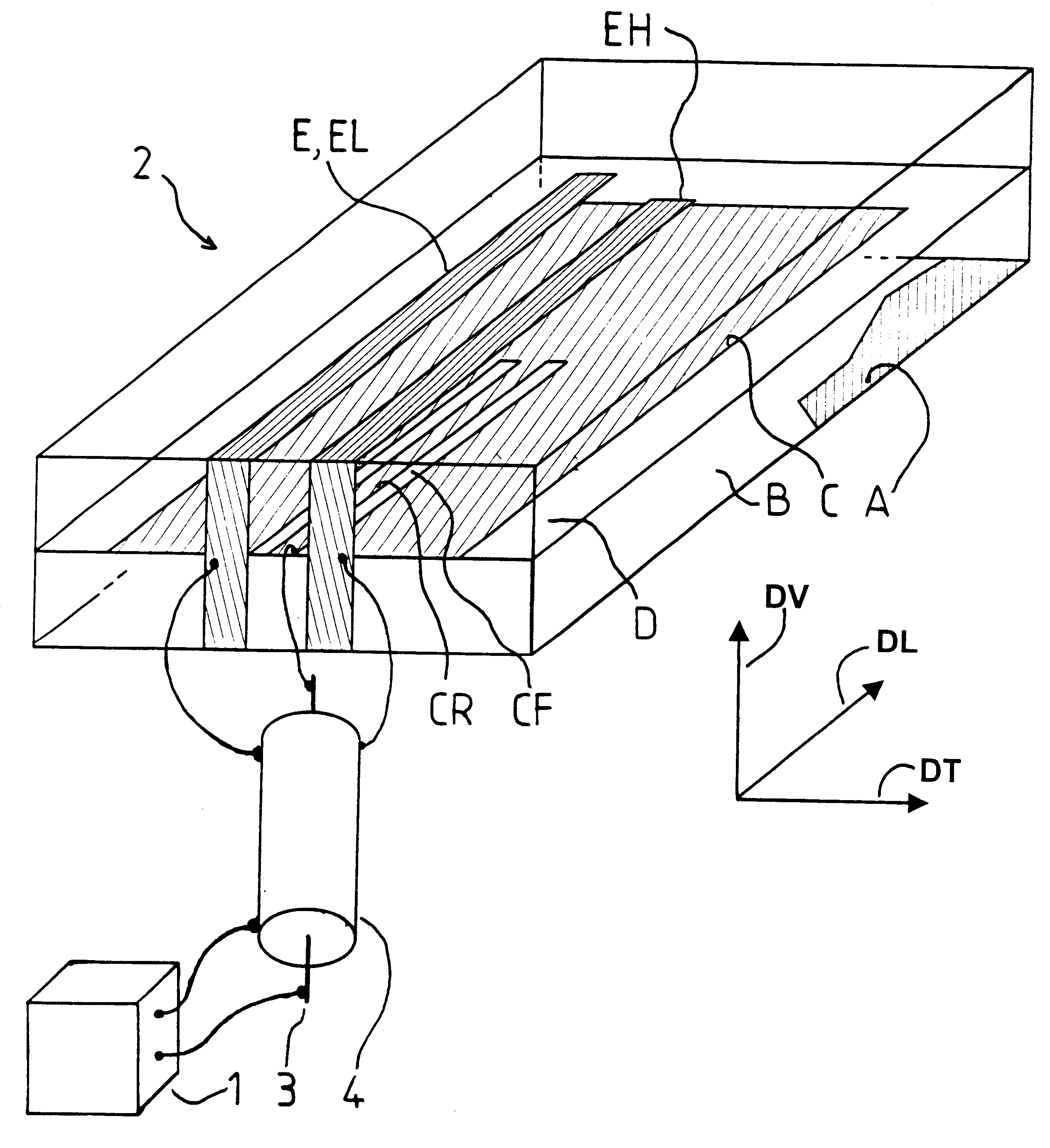
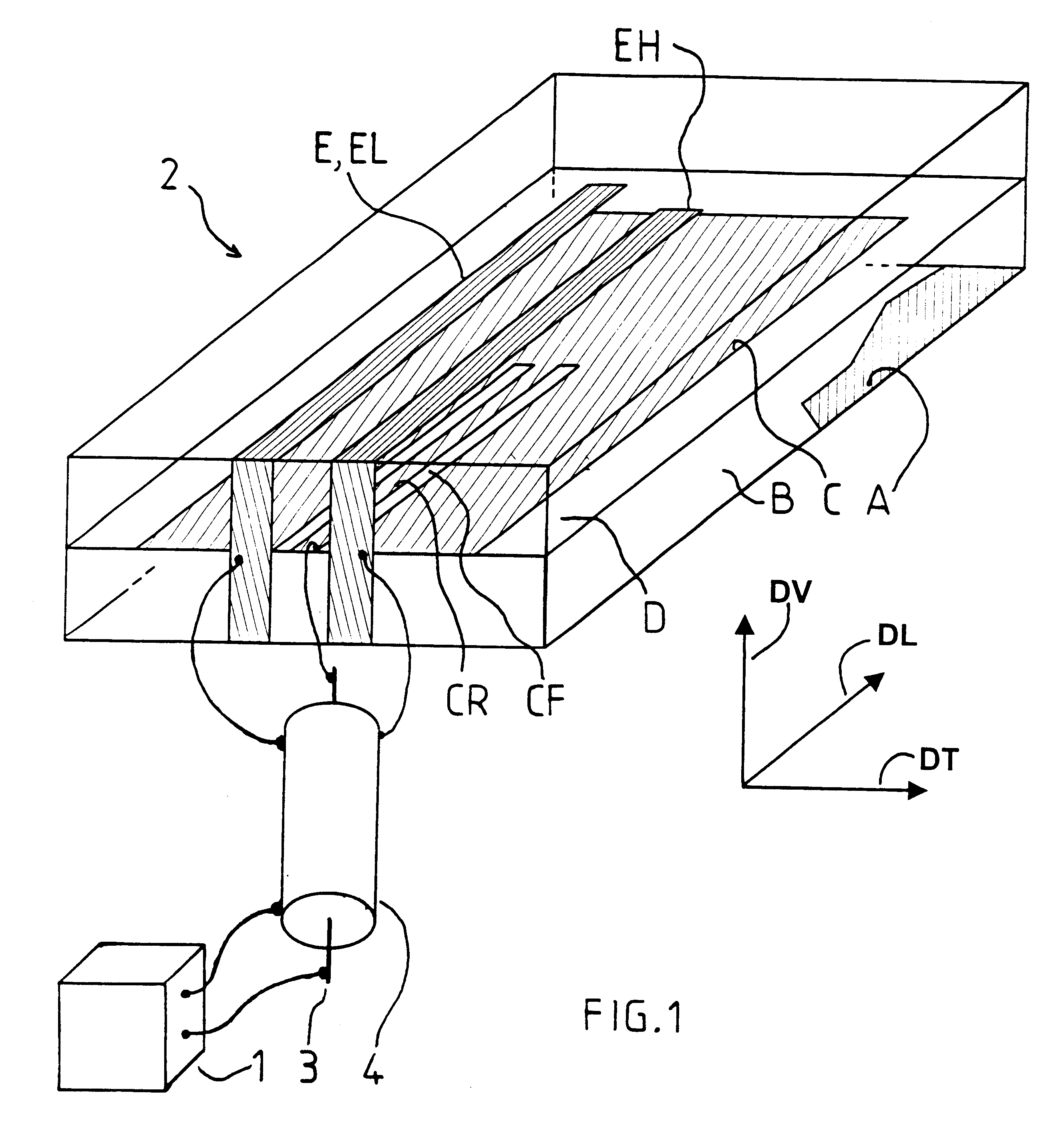
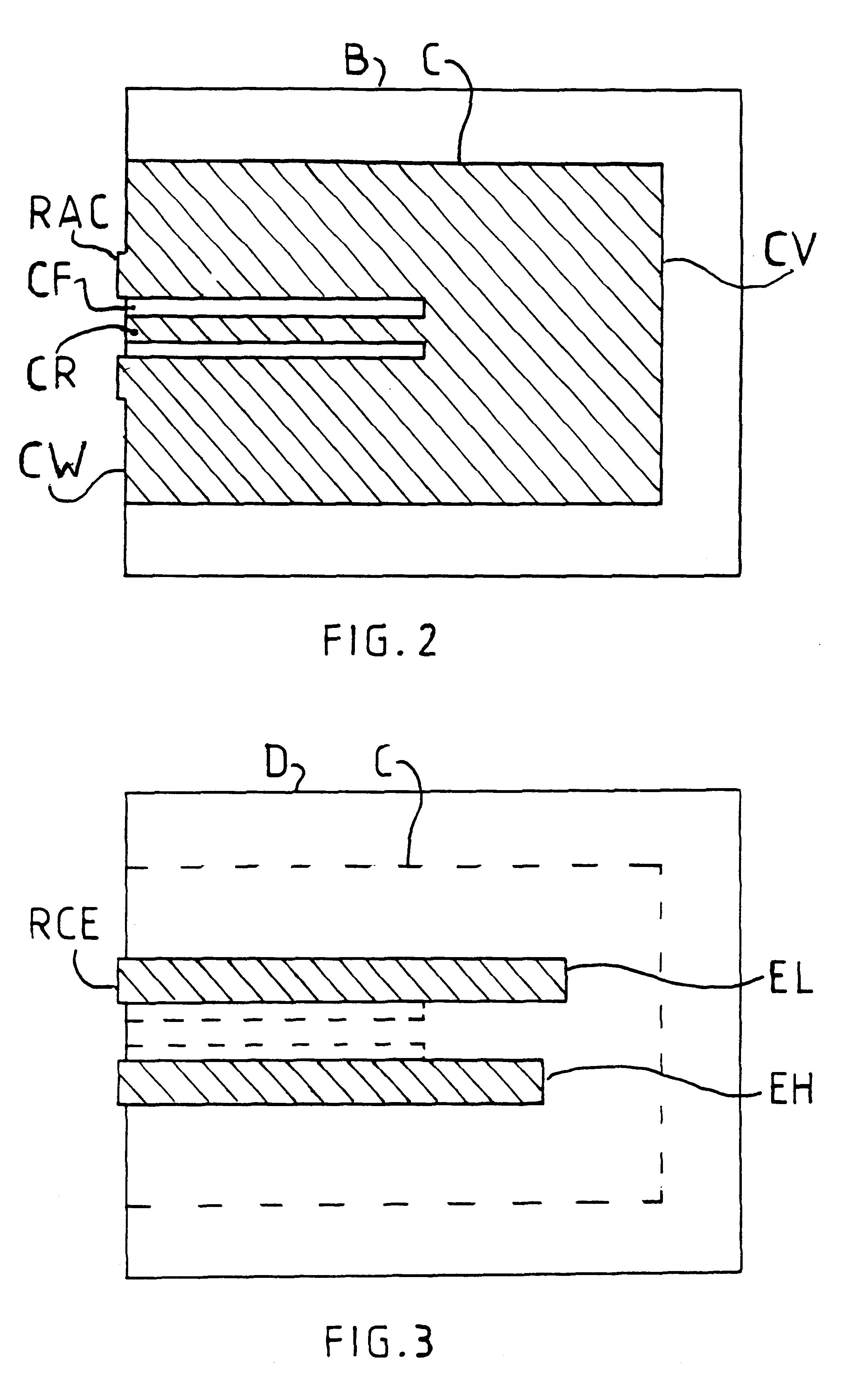
In the figures, thin metal layers on the surface of dielectric layers are shaded. In FIG. 1, to simplify the drawing, the dielectric layers are represented as if they were transparent, in order to show the underlying layers, and the shading representing the bottom conductive layer is limited to part of that layer.

Referring to FIG. 1, three mutually crossing axes respectively constitute a longitudinal axis DL, a transverse axis DT and a vertical axis DV of an antenna and the longitudinal and transverse axes are horizontal axes. The above terminology is employed to facilitate the description and is without regard to the direction of the gravitational field. The longitudinal axis has a forward direction, which is that of the arrow DL, and a retrograde direction opposite the forward direction. The antenna includes a plurality of layers A, B, C, D, E, forming a succession in the vertical direction. Each layer, such as the layer C, has an area extending in said direction DL of the longitu...


PUM


Abstract

An antenna with stacked resonant structures includes: a guide line for guiding electromagnetic waves formed in a conductive layer lying in a plane, and two resonant structures having different resonant frequencies, the two structures being formed on respective opposite sides of the plane so that both are coupled directly to the line and substantially decoupled from one another by the conductive layer. The guide line is preferably of the coplanar type and the two resonant structure are preferably of the quarter-wave type. The invention applies in particular to dual-band mobile telephones.

Description

The invention relates to radiocommunications. It relates more particularly to radiocommunications system antennas, and even more particularly to planar antennas. Planar antennas are included in various types of equipment, such as mobile telephones, mobile telephone base stations, automobiles, aircraft, and missiles. In the case of mobile telephones, the continuous ground plane of the antenna provides an easy way to limit the level of radiation intercepted by the body of the user of the equipment. In the case of automobiles, and above all in the case of aircraft and missiles, whose outside surface is made of metal and has a curved profile to limit aerodynamic drag, a planar antenna can be conformed to that profile so as not to cause unwanted additional aerodynamic drag.In such applications the antenna must be compact but it is nevertheless often required to be able to use several operating frequencies in the radio and microwave frequency bands. The frequencies can be close together a...

Claims


Application Information

Patent Timeline
Patent Type & Authority Patents(United States)
IPC IPC(8): H01Q1/24H01Q5/00H01Q9/04H01Q21/30H01Q1/38H01Q5/10H01Q5/385H01Q13/08
CPCH01Q1/242H01Q9/0407H01Q5/385H01Q9/0421H01Q9/045H01Q9/0414
Inventor HERVE, PASCALKOUAM, CHARLES NGOUNOUCOUPEZ, JEAN-PHILIPPE
Owner ALCATEL LUCENT SAS
Why Eureka
Try Eureka