Method of bonding cast superalloys

a superalloy and bonding technology, applied in the field of blades and vanes, can solve the problems of inability to produce defect-free large components in any significant yield, inability to bond inability to achieve the bonding technology of advanced single crystal-containing superalloys, such as cmsx-4, targeted for use in ats-class engines

Inactive Publication Date: 2001-12-04
SIEMENS ENERGY INC
View PDF43 Cites 64 Cited by
  • Summary
  • Abstract
  • Description
  • Claims
  • Application Information

AI Technical Summary

Problems solved by technology

Although components with such features have been developed for aircraft engines, the larger size of power generation turbine components provides a crucial challenge.
To date, casting trials have been unable to produce defect-free large components in any significant yields.
Currently, however, the required bonding technology for advanced single crystal-containing superalloys, such as CMSX-4, that are targeted for use in ATS-class engines is not available.
Moreover, while high radial stresses can occur on this plane, the stresses across the bonding surfaces are low.
Furthermore, some expensive elements such as rhenium may not be desired in the foil in order to reduce costs.
Furthermore, the stresses created by these profiling techniques must be sufficiently low such that they do not induce recrystallization from the deformed layer of cold work during subsequent thermal cycles, including bonding and heat treatment.
Such ground surfaces do not contain sufficient stored plastic work to cause recrystallization in the near surface region.
Because of the large size of land-based turbine components, very small distortions from design specifications can produce large absolute deviations from the desired parts profiles.
While these offsets are significant in single piece castings, in the production bonded parts they become critical because of their influence on the relative fit-up between parts.
Effectively, very small relative distortions between two parts can produce very large gaps that may be inadequately or incompletely filled by the bonding process.
For nickel base single crystals used in turbine components, such working can include bending, indenting, chipping by metal working tools and even excessively severe cleaning by grit or shot blasting.
The damage induced by these processes can cause recrystallization when they precede the solution treatment at about 2,400.degree. F. that is required for such single crystals.
However, changing the part and the mold will not account for run-to-run variations and non-systematic deviations from the desired profile.
While polycrystalline alloys can be mechanically straightened at room temperature, conventional processing of single crystals avoids such mechanical deformation because of the danger of recrystallization.
This process involves high temperature low strain rate deformation (similar to superplastic deformation) that causes distortion of the part without incurring sufficient deformation damage to impart recrystallization.
Much of this cost saving occurs because the SC alloys contain expensive rhenium, whereas the polycrystalline alloys do not contain this element.
Using materials that are less well matched may produce deleterious phases in the bond zone and concomitant reduction in properties.
Since polycrystalline and single crystal alloys typically have different chemical compositions, identical matching of the bond foil composition to each side of a single crystal-to-polycrystal bond joint is not possible.
In particular, it is generally not be possible for the conventionally cast polycrystalline material to withstand the high solution heat treat temperatures employed for the single crystal material.

Method used


Image

  • Method of bonding cast superalloys

Examples


Embodiment Construction

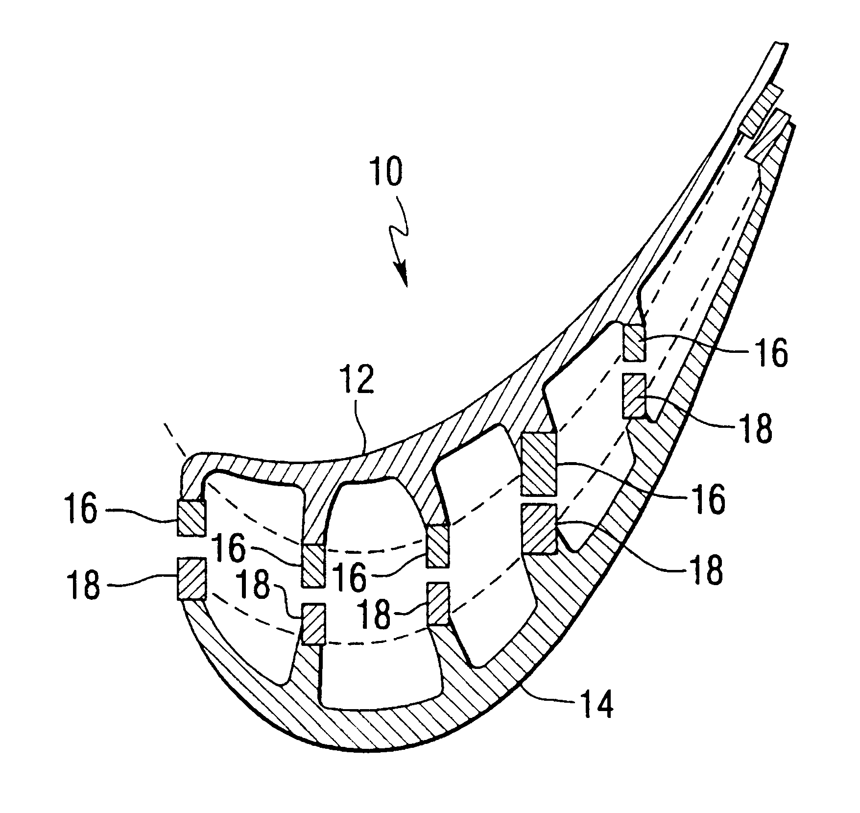
The effect of bonding foil chemistry and thermal treatments on the microstructure and mechanical properties were assess experimentally. Initially, several bonding foil chemistries and thermal processes were employed to generate samples for metallographic assessment. The processes that produced the most homogeneous chemistry and microstructure across the bond line and throughout the base metal were selected for further assessment by testing the tensile and creep properties.

CMSX-4 base material was supplied in the as-cast conditions as single crystal slabs approximately 9.5.times.76.2.times.152.4 mm (0.375.times.3.times.6 inches). The bonding media were obtained as 50 .mu.m (0.002 inch) thick commercial bonding foils.

The boron levels of the bonding foils are actually B ranges since two of the foils were supplied in several forms with slightly different boron levels: Ni-Flex 110 was supplied with 1.3%, 1.7% and 2.5% B levels and Ni-Flex 120 was supplied with 1.5%, 1.7% and 1.9% B level...


PUM

PropertyMeasurementUnit
thicknessaaaaaaaaaa
widthaaaaaaaaaa
temperatureaaaaaaaaaa

Abstract

A method of bonding cast superalloys is disclosed. The method includes the steps of casting separate superalloy component parts, machining the mating surfaces of the separate parts in a controlled manner to avoid recrystallization of the material and to ensure a tight fit between the parts, bonding the parts together, and thermally treating the bonded component. In a preferred embodiment, the component is a turbine blade for a land-based gas turbine.

Description

The present invention relates to bonding of cast superalloys, and more particularly relates to a method of bonding cast superalloy components for turbines and the like.BACKGROUND INFORMATIONState-of-the-art blades and vanes that are employed in modern, high efficiency power generation combustion turbine engines rely on high quality materials such as single crystal alloys and precise control of the part's internal and external dimensions. Because of the large size of these parts, cost-effective manufacturing is being pursued by several routes.Land-based gas turbines, such as the advanced turbine system (ATS) which is under development, require cost-effective high performance components fabricated from advanced materials. First and second row turbine blades and vanes include complex internal and external geometries, and should be fabricated from defect-free materials. Although components with such features have been developed for aircraft engines, the larger size of power generation t...

Claims


Application Information

Patent Timeline
Patent Type & Authority Patents(United States)
IPC IPC(8): B23K20/16B23K20/02B23K20/22B23K35/30B23P15/04C22C19/05C22F1/10C30B11/00F01D5/28F01D5/14F01D5/18
CPCB23K20/023B23K20/16B23K20/22B23K35/3033B23P15/04C22C19/057C22F1/10C30B11/00F01D5/147F01D5/184F01D5/28C30B29/52B23K35/304B23K2201/001Y02T50/671Y02T50/676F05D2230/23F05D2230/40F05D2300/607B23K2101/001Y02T50/60
Inventor BURKE, MICHAEL A.FREYER, PAULA D.HEBBAR, MOHAN A.SETH, BRIJ B.SWARTZBECK, GARY W.ZAGAR, THOMAS WALTER
Owner SIEMENS ENERGY INC
Why Eureka
Try Eureka