Adaptive interface apparatus and method for data terminal elements in a communication network transmitting and receiving ethernet over a shielded twisted pair cabling system

a technology of data terminal elements and adaptive interfaces, applied in the field of interface apparatus and methods of communication networks, to achieve the effect of facilitating the connection of a workstation

a technology of data terminal elements and adaptive interfaces, applied in the field of interface apparatus and methods of communication networks, to achieve the effect of facilitating the connection of a workstation

US6332166B1Inactive Publication Date: 2001-12-18IBM CORP

Image

  • Adaptive interface apparatus and method for data terminal elements in a communication network transmitting and receiving ethernet over a shielded twisted pair cabling system
  • Adaptive interface apparatus and method for data terminal elements in a communication network transmitting and receiving ethernet over a shielded twisted pair cabling system
  • Adaptive interface apparatus and method for data terminal elements in a communication network transmitting and receiving ethernet over a shielded twisted pair cabling system

Examples


Embodiment Construction

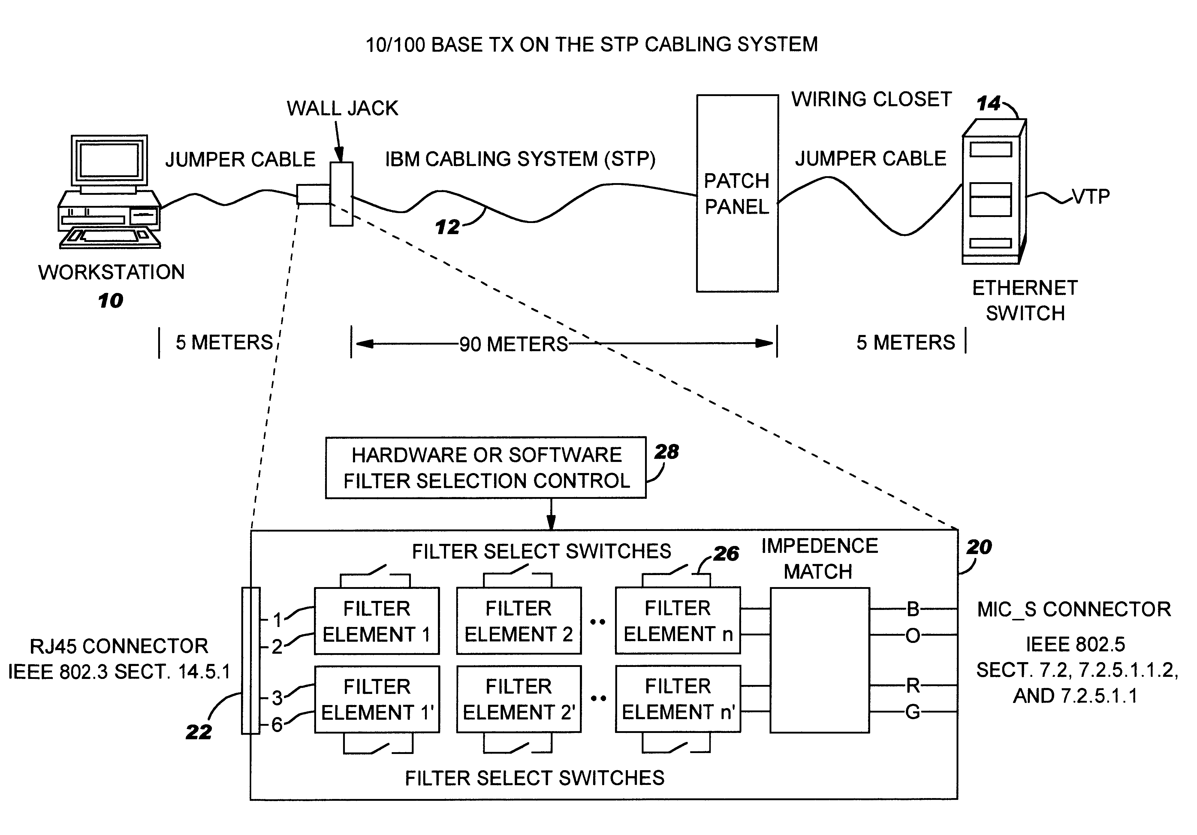
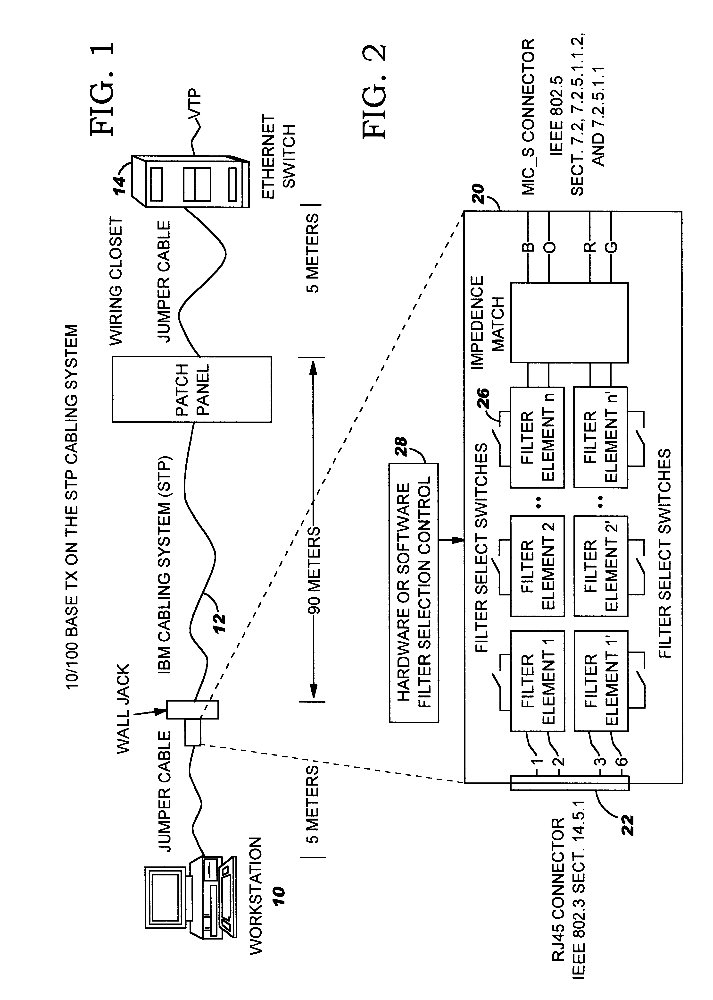
In FIG. 1 a workstation or data terminal element 10 normally connected to a token ring network (not shown) through a Standard Twisted Pair (STP) cabling system 12 may also be connected through the STP cabling system and a switch 14 to an Ethernet installation (not shown) using Untwisted Pair (UTP) cabling. Normally the workstation 10 is within 5 meters of a standard RJ 45 telephone connector coupling the workstation to the token ring network in accordance with IEEE Standard 802.3, Section 14.5.1. Likewise, workstations coupled to the Ethernet installation employ a standard RJ 45 telephone connector but the pin out configuration for UTP cabling is different than the pin out configuration for the STP cabling system. Likewise, the characteristic impedance of the STP cabling system, which is 150 ohms, is different than the UTP cabling system, which is 100 ohms. Moreover, Ethernet transceivers have adaptive algorithms designed for equalization and attenuation settings for signal improvem...


PUM


Abstract

An adaptive interface and method of operation facilitate connection of a work station in a Local Area Network (LAN) using Shielded Twisted Pair (STP) cabling to an Ethernet 10 / 100BASE TX installation using Unshielded Twisted Pair (UTP). The work station is coupled through the adaptive interface to the STP cabling system emulating a given number of meters of UTP cabling. The interface adapter comprises at one end a RJ 45 connector adapted for connection to the STP cabling and at the other end a MIC_S token ring connector coupled to an Ethernet adapter through the STP cabling system. The adaptive interface includes programmatically controlled filters interconnecting the RJ 45 and MIC_S connectors. The filter comprises a series of 1 . . . N switchable lumped passive element units which can be sequentially connected into the STP cabling to emulate the amplitude attenuation and phase shift of a preselected length of UTP 5 cabling, typically in the range of 20 meters. In operation, the Physical Layer (PHY) in the communication system enters a start up sequence for the various circuits and cabling in the layer. During the start up sequence, the adaptive interface is bypassed. After an appropriate delay to allow PHY convergence or a bit error rate measurement, the PHY transmit / receive signals are examined for bit errors by a test unit. If there are no bit errors, no filter element is inserted in the STP cabling by the adaptive interface and the work station is coupled to the Ethernet installation. If there are bit errors, a first filter element is switched into the STP cabling by the adaptive interface. The bit error signals are re-examined. If there are no errors, the workstation is connected to the Ethernet installation. If bit errors continue to exist, the next element(s) of the filter is inserted into the STP cabling until the "Nth" filter element is reached. If bit errors continue to exist on the STP cabling after inserting the Nth filter in the STP cabling, a re-try test sequence is initiated by the adaptive interface and the start up sequence is repeated. If re-try is not initiated, a transmit error is displayed and the workstation / Ethernet installation cannot proceed without modification. A diagnostics menu is displayed and a set-up process determines with human intervention what system changes are needed for the workstation / Ethernet connection.

Description

1. Field of Invention:This invention relates to interface apparatus and methods of operation in communication networks. More particularly, the invention relates to adaptive interface apparatus and methods for data terminal elements transmitting and receiving Ethernet over a shielded twisted pair cabling system.2. Description of Prior Art:Many customers have installed Shielded Twisted Pair (STP) cabling systems. The systems have specific characteristics based on a 150 ohm STP wire with hermaphroditic data connectors, and a standard RJ 45 telephone connector with a unique pin out. The system further includes a large data connectors installed at an office wall connector and has the RJ 45 telephone connector in a wiring closet. Workstations in these offices typically have token ring adapters with cables that attach them from the workstation adapter to the telephone connector in the office wall connector and wiring closet.Ethernet installations include 10 / 100BASE T Ethernet adapters, whi...

Claims


Application Information

Patent Timeline
18 Dec 2001
Publication
US6332166B1
IPC
H04M11/06; H04L25/02
CPC
H04L25/0278; H04L25/0286; H04M11/062; H04L25/0272; H04L25/0292
Inventors
CRANFORD, JR., HAYDEN CLAVIE; EFFERSON, JR., JOSEPH RONALD