

Shaft seal and turbine using the same
- Summary
- Abstract
- Description
- Claims
- Application Information
AI Technical Summary
Benefits of technology
Problems solved by technology
Method used
Image

Examples
first embodiment
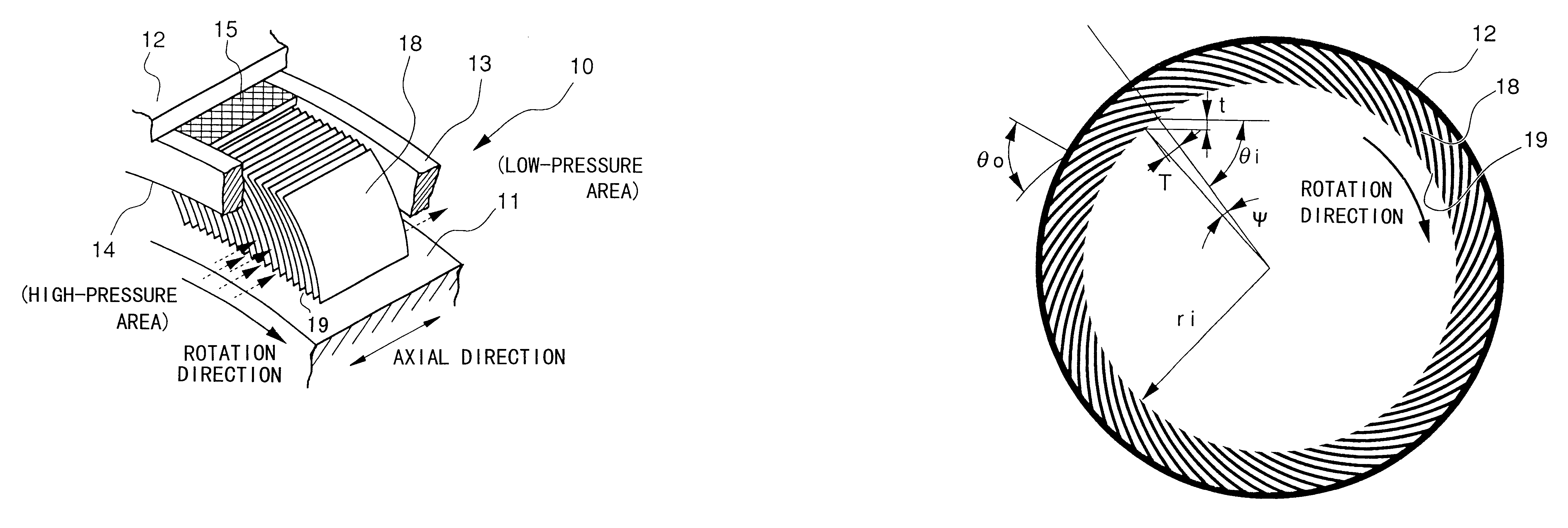
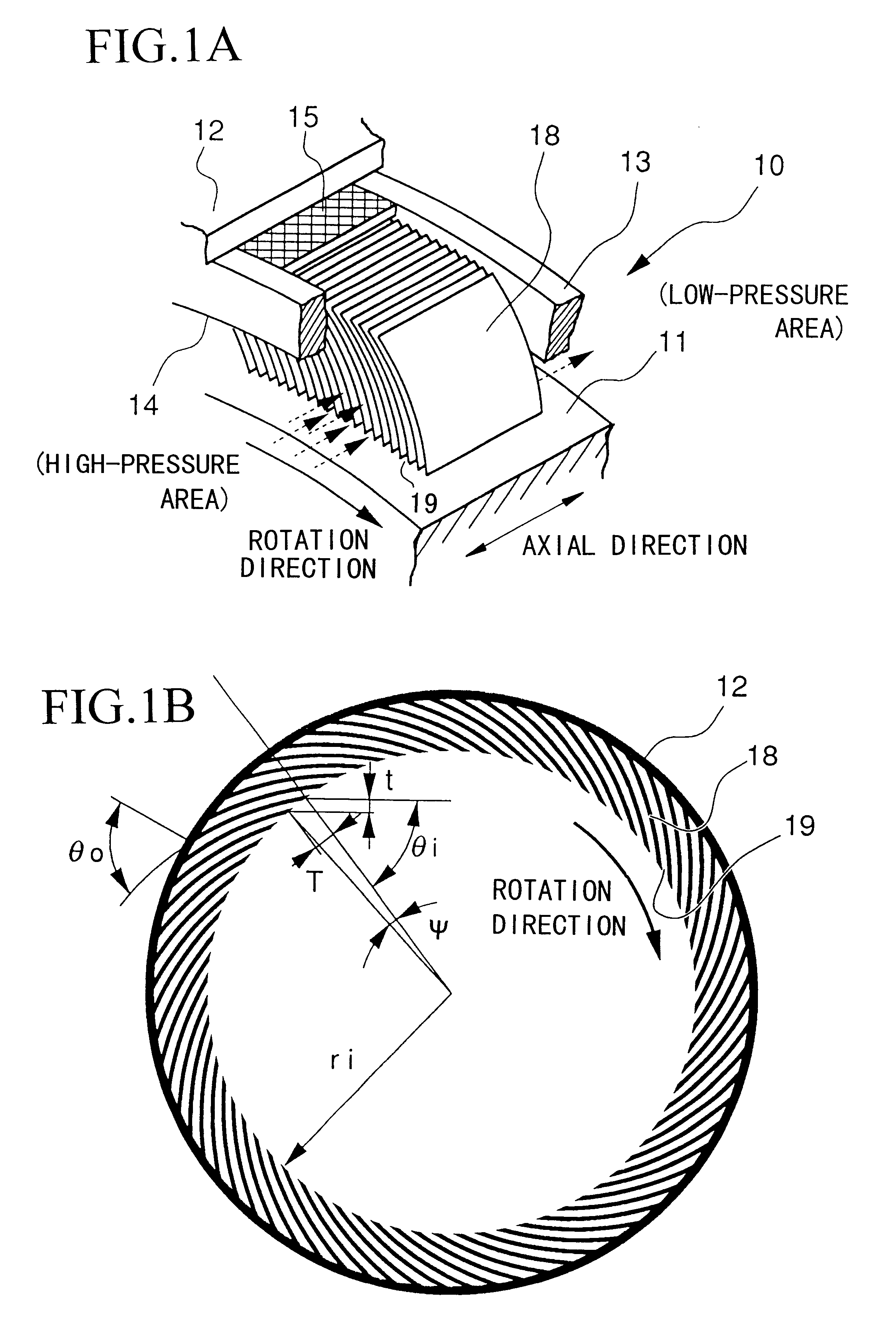
The structure of the shaft seal and the gas turbine as the first embodiment will be explained with reference to FIGS. 1A, 1B and 2.
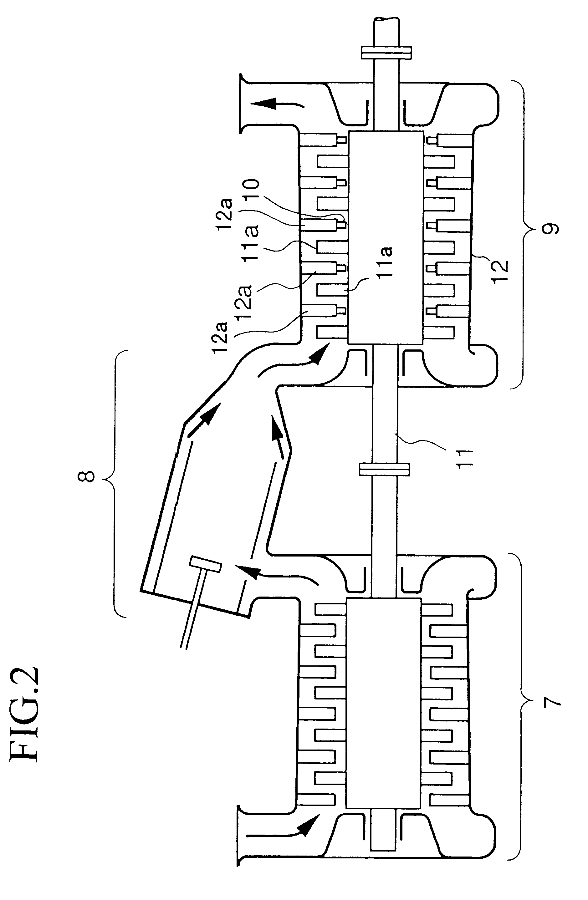
FIG. 2 shows the general structure of the gas turbine. In the figure, reference numeral 7 indicates a compressor, reference numeral 8 indicates a combustor, and reference numeral 9 indicates a turbine. The compressor 7 draws in a large amount of air and compresses it. In general gas turbines, a part of the power obtained using the rotation shaft (i.e., shaft 11 explained later) is used as the power of the compressor. The combustor 8 makes the compressed air (compressed by the compressor 7) burn by mixing the air with fuel. The turbine 9 draws in the combustion gas generated by the combustor 8 and makes the air expand, and blasts the expanded air against the moving blades 11a fixed to the rotation shaft 11, so as to convert the thermal energy of the combustion gas into the mechanical rotational energy and to generate the power.
In addition to the moving bl...
second embodiment
Below, the structure of the gas turbine as the second embodiment according to the present invention will be explained. The basic structure of the present gas turbine and leaf seal is the same as that of the first embodiment, and structural elements corresponding to each other have the identical reference numerals, and explanations thereof are omitted. That is, each effect described above can also be obtained in the present embodiment. In addition, a similar omission will be performed in the following embodiments.
FIGS. 4A to 4C show the structure of leaf seal 10 of the second embodiment. FIG. 4A is a perspective view showing the structure of the leaf seal, FIG. 4B is a cross-sectional view showing the leaves as the constituents of the leaf seal, and FIG. 4C is a partially enlarged view for explaining a distinctive portion of FIG. 4B.
In the present embodiment, leaves 18 of leaf seal 10 are attached to casing 11 in a manner such that angle .alpha. between the rotation direction and the...
third embodiment
Below, the structure of the gas turbine as the third embodiment according to the present invention will be explained.
The leaf seal 10 provided in the present gas turbine has the same basic structure as that shown in FIG. 4A of the above second embodiment, that is, the leaves 18 are attached to casing 11 in a manner such that angle .alpha. between the rotation direction and the peripheral surface of the rotation shaft 11 is a predetermined acute angle.
In addition to that, as shown in FIG. 5C (partially enlarged view), the top-end portion of each leaf 18 (i.e., at the rotation shaft 11 side) has slope 2018a functioning as the buoyancy providing means of the present invention. In this slope 2018a, the distance between the top point of the leaf and the peripheral surface 511a of the rotation shaft 11 gradually decreases along the rotation direction, and the angle .beta. with respect to the peripheral surface 511a is very small.
According to the above structure, when the rotation shaft 11...
PUM
 Abstract
Description
Claims
Application Information