
High dispersion, laser protection lens

a laser protection and high dispersion technology, applied in non-linear optics, instruments, blood vessels, etc., can solve the problem of not being able to achieve the effect of avoiding laser protection lenses as effectively as possible, and achieve the effect of reducing the intensity of received laser radiation

Inactive Publication Date: 2002-02-05
SMITH DAVID C
View PDF1 Cites 3 Cited by
  • Summary
  • Abstract
  • Description
  • Claims
  • Application Information

AI Technical Summary

Benefits of technology

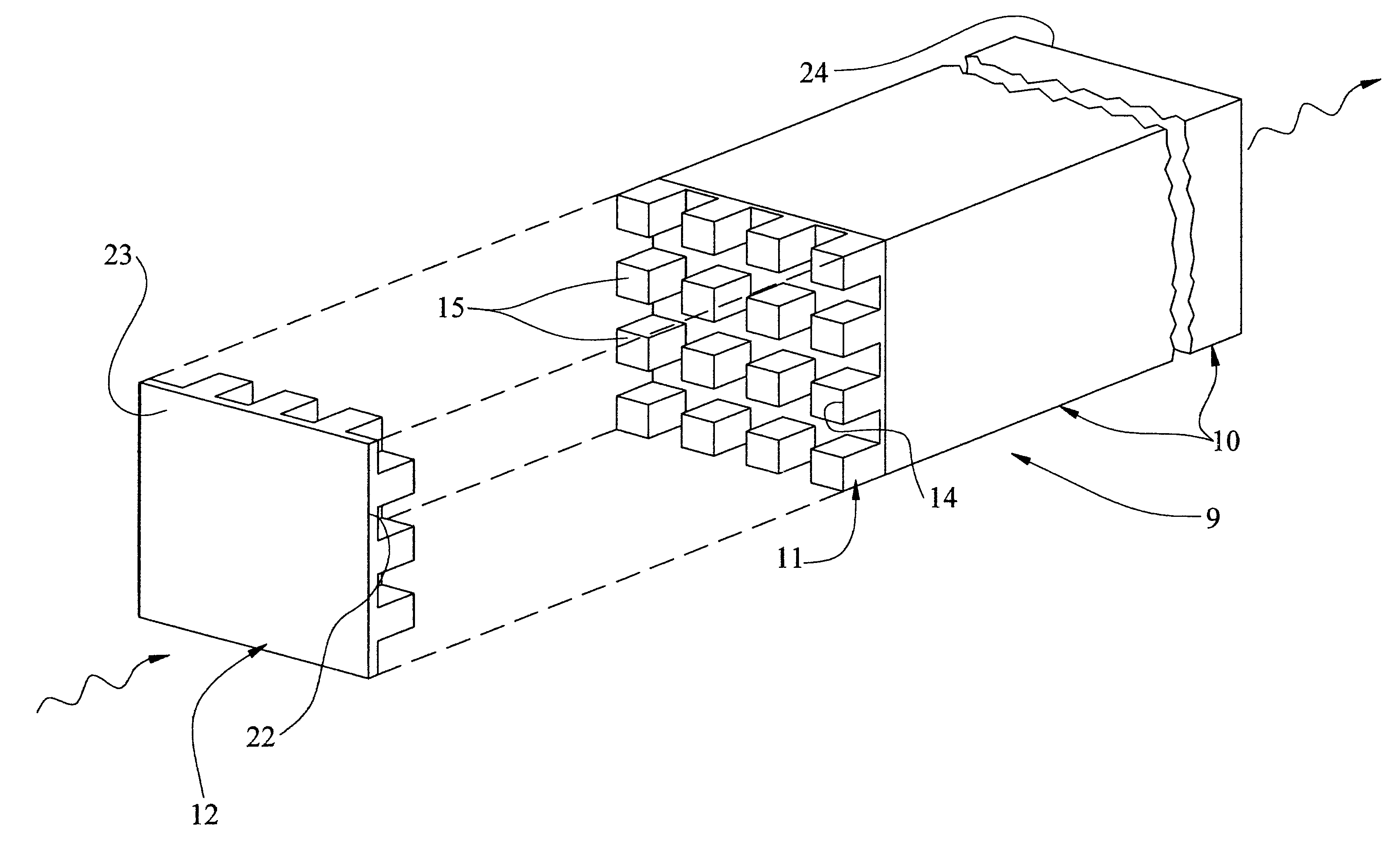
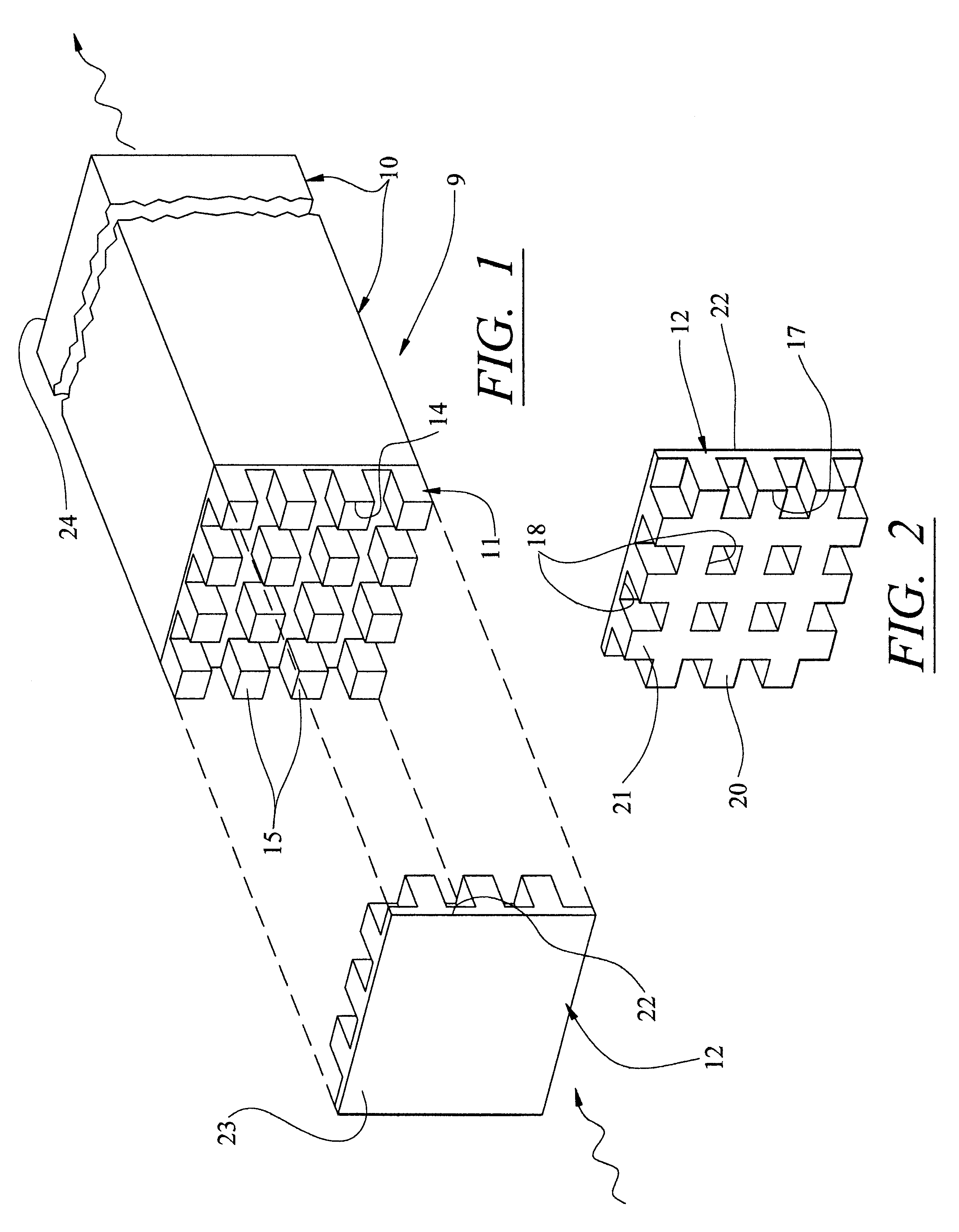
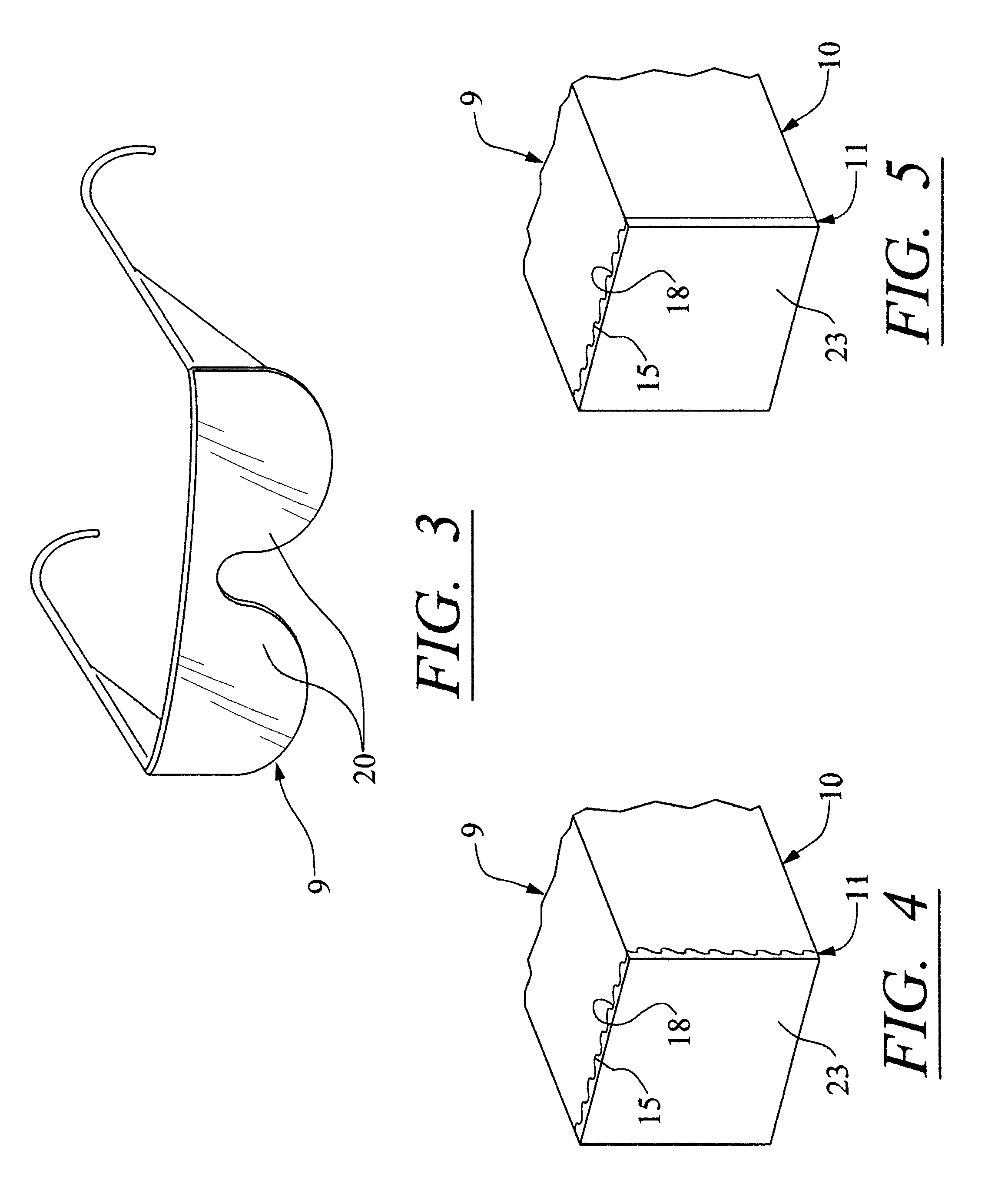
According to the present invention, a lens for protecting optical systems having high optical gain, such as the human eye and optical instruments of high optical gain, induces thermal blooming of laser radiation passing therethrough by means of phase distortion created by a spatially-varying absorption or reflection characteristic.
An important aspect of the present invention is the potential to utilize vapor deposited reflecting elements, which may be quite thin, and have low weight. Such elements are easily made in virtually any pattern which can be achieved by low cost, conventional vapor deposition techniques.

Problems solved by technology

It has been determined that the foregoing laser protection lens is not as effective as possible, particularly per unit of axial thickness of the lens (parallel to the path of radiation to the eyes or instruments being protected thereby).

Method used


Image

  • High dispersion, laser protection lens
  • High dispersion, laser protection lens
  • High dispersion, laser protection lens

Examples


Embodiment Construction

One principle of the invention is that the incoming radiation of a wavelength for which there is significant absorption in the absorption-portion of the lens will raise the temperature of the lens, thereby changing its index of refraction, and therefore altering the phase of the radiation as it exits the lens. If adjacent portions of the lens have absorption-portions of differing absorption, then the radiation exiting those different portions will be at different phases, and will therefore interfere, producing thermal blooming, which will disperse the radiation away from a focal point, thereby lowering the flux density of radiation at a point of interest, such as the retina or the light responsive portion of an optical equipment. The change in phase of radiation passing through the absorbing medium of the invention is given as ##EQU1##

where:

.DELTA..phi.=the change in phase due to absorption raising the temperature and thus changing the index of refraction

.mu..sub.T =the temperature ...


PUM


Abstract

A lens includes a medium which absorbs laser radiation that may be harmful to the eye or other high gain optics raising its temperature and thereby changing its index of refraction, adjacent to a medium which does not absorb that radiation thereby providing a spatially fluctuating variation in total phase change, which causes interference and thermal blooming that disperses the radiation sufficiently to lower the intensity at the retinal spot (or optics to be protected) below that which would cause damage. Or, reflective surfaces on absorbing material have the same effect. Volumes which absorb or reflect laser radiation of a given band of frequencies are interspersed with volumes which do not absorb or reflect laser radiation of that given band of frequencies; the second volumes may be non-absorbing and non-reflecting, or may absorb laser radiation of a second band of frequencies. The fluctuation in absorption is small compared to total absorption, thereby to provide elements of radiation having different phases but sufficiently similar intensities. Two (or more) layers of absorbers provide protection from four (or more) bands of frequencies. Lead glass is used, for increased change in index as a function of temperature; and absorbing polycarbonate plastic is used for a lens substrate.

Description

This invention relates to three dimensional, periodic absorption, phase change dispersing lenses having a near-unity intensity ratio for maximal laser dispersion.In U.S. Pat. No. 5,831,769, a lens includes a medium which absorbs laser radiation that may be harmful to the eye or other high gain optics, raising its temperature and thereby changing its index of refraction in a pattern, which causes a phase change in the radiation passing therethrough. The medium may be periodically bounded by thermal sinks, thereby providing a periodic differential in temperature rise, may be provided in a length of absorption material which varies periodically or may have a density of absorption material which varies periodically, thereby to have a periodic absorption characteristic. The periodicity, which may be regular or random, provides a periodic variation in total phase change, which causes interference (thermal blooming) that disperses the radiation sufficiently to lower the intensity at the re...

Claims


Application Information

Patent Timeline
IPC IPC(8): G02B3/00G02B5/02H01S3/00A61F2/06A61F2/90
CPCG02B3/00H01S3/005G02B5/26G02B5/223A61F2/91
Inventor SMITH, DAVID C.
Owner SMITH DAVID C
Learn More