The present invention is directed to a low closure force gasket for environmental sealing and / or
electromagnetic interference (EMI) shielding which is especially adapted for use in smaller electronic
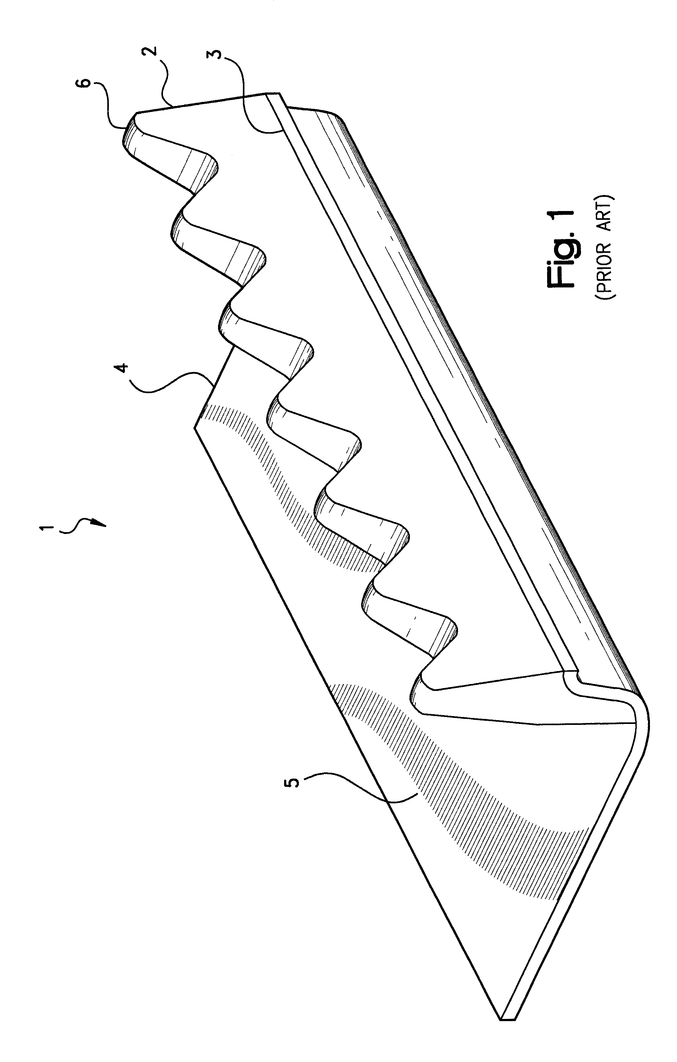
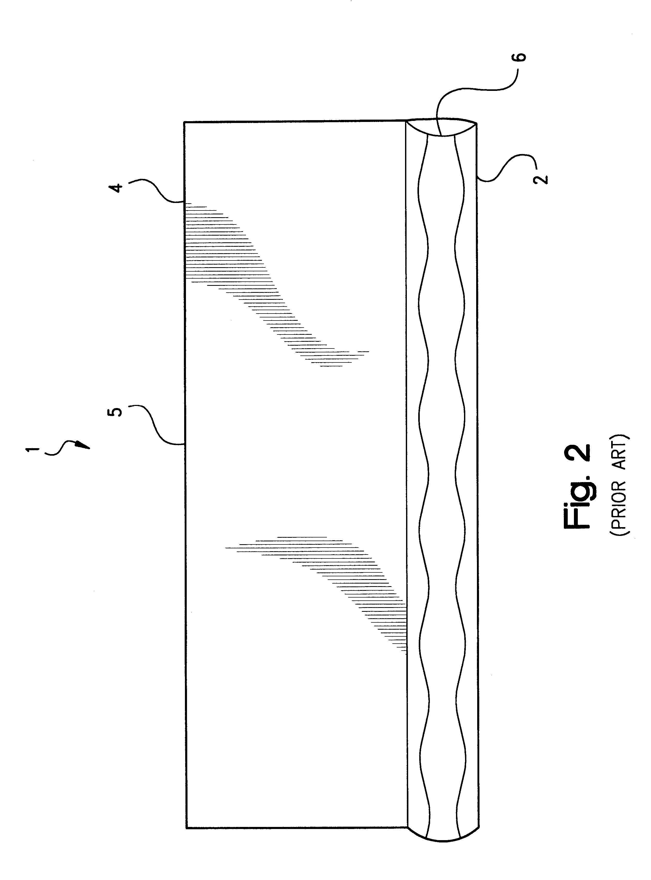
enclosure packages. As in conventional designs, the gasket of the present invention is configured as having an apex surface which is formed, relative to the housing or other substrate on which the base of the gasket may be supported, to exhibit a sinusoidal or other "waveform" profile to be responsive to lower closure force loads when compressed intermediate a pair of surfaces such as between two halves of a housing. However, the gasket of the invention further is configured, such as in having, for example, at least one lateral surface which is formed, relative to the apex surface, as a transverse waveform profile, to exhibit a controlled deflection response which may be characterized as a
bending moment. Such response advantageously provides a large but controlled deflection affording a more uniform interface contact with the contacting surface for more assured electrical and physical continuity and, in turn, more reliable EMI shielding and environmental sealing effectiveness. When employed, for example, in
electronics applications, the gasket of the invention therefore provides consistent EMI shielding and, additionally, environmental sealing effectiveness.
Advantages of the present invention therefore include the provision of an improved gasket profile for low closure force applications such as may be found in small, handheld electronic devices. Additional advantages includes a gasket profile which exhibits a controlled deflection response for more stable interface contact with the housing or circuit board components of the
enclosure and, in turn, more assured electrical continuity and reliable EMI shielding effectiveness. These and other advantages will be readily apparent to those skilled in the art based upon the disclosure contained herein.
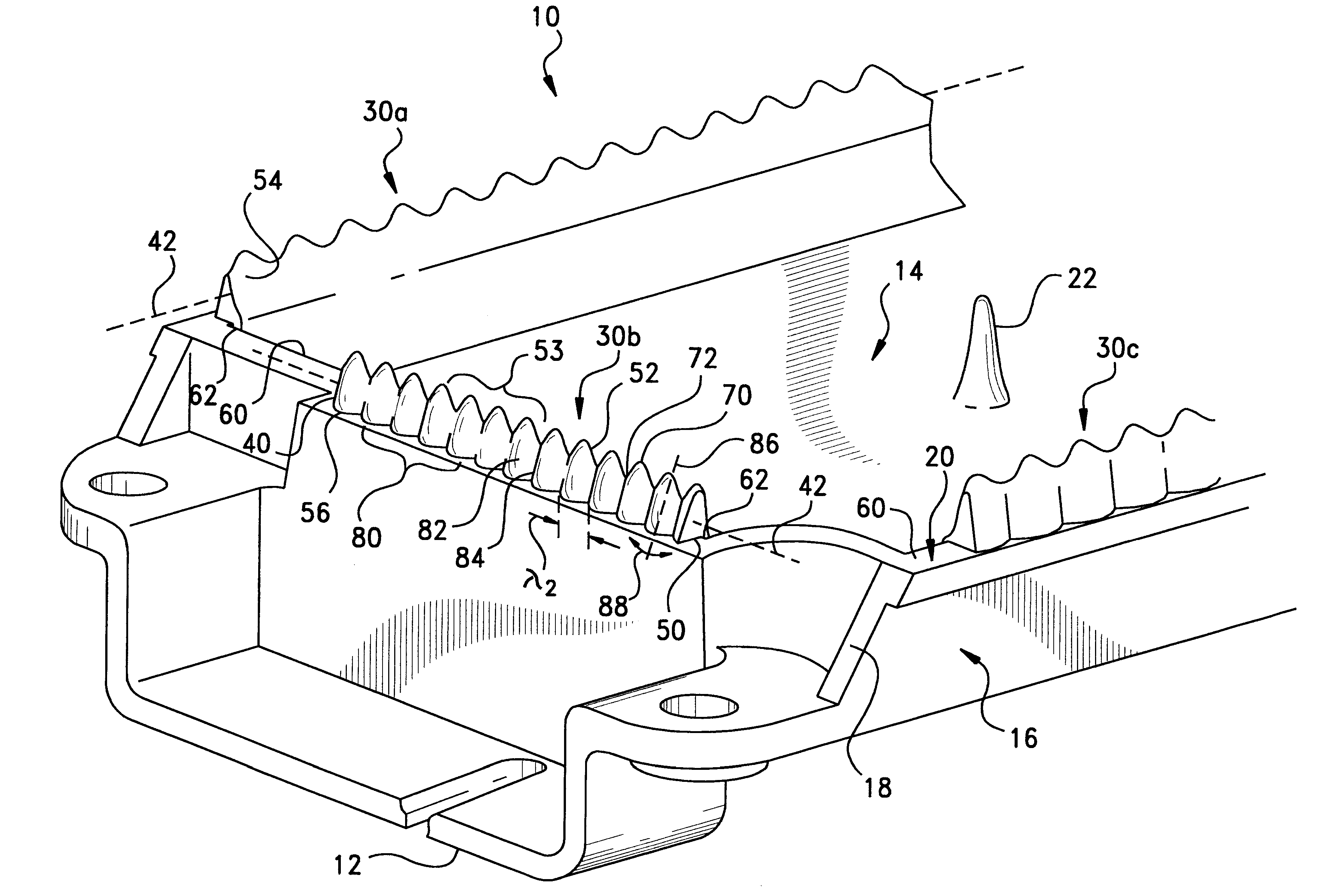
As may be seen with additional reference to the magnified views of FIGS. 5 and 6, a resilient gasket, the constitute segments of which are referenced at 30a-d, is molded or otherwise retained, such as by
adhesive bonding or an
interference fit, on side wall 18 and optionally, internal wall 26, to be compressible axially under a predetermined
compressive load intermediate
edge surface 20 and the corresponding surface of the
mating housing part (not shown in FIGS. 4-6). In this regard, gasket 30 preferably is overmolded onto the sidewall
edge surface 20 by injection or
compression molding as formed of an elastomeric material which specifically may be selected for temperature, chemical, or physical compatibility with the housing material. Depending then upon the application, suitable materials may include natural rubbers such as Hevea, as well as
thermoplastic, i.e., melt-processible, or thermosetting, i.e., vulcanizable, synthetic rubbers such as fluoropolymers, chlorosulfonate,
polybutadiene,
polybutadiene, buna-N, butyl,
neoprene,
nitrile, polyisoprene,
silicone, fluorosilicone,
copolymer rubbers such as
ethylene-propylene (EPR),
ethylene-propylene-
diene monomer (EPDM),
nitrile-butadiene (NBR) and
styrene-butadiene (SBR), or blends such as
ethylene or propylene-EPDM, EPR, or NBR. The term "synthetic rubbers" also should be understood to encompass materials which alternatively may be classified broadly as
thermoplastic or thermosetting elastomers such as polyurethanes, silicones, fluorosilicones,
styrene-
isoprene-
styrene (SIS), and styrene-butadiene-styrene (SBS), as well as other polymers which exhibit rubber-like properties such as plasticized nylons, polyesters, ethylene vinyl acetates, and polyvinyl chlorides. As used herein, the term "elastomeric" is ascribed its conventional meaning of exhibiting rubber-like properties of compliancy, resiliency or compression deflection, low
compression set, flexibility, and an ability to recover after deformation.
Outboard lateral surface 56, in turn, similarly extends intermediate the base surface and apex surfaces 50 and 52 opposite the inboard lateral surface 54. As may be seen with reference to the enhanced view of FIG. 6, outboard lateral surface 56 preferably is inclined along axis 76 from the base surface 50 to the apex surface 52 in the direction of the inboard lateral surface 54 so as to form an
acute angle, referenced at .theta., with a
vertical axis, 78. Such inclination of the lateral surface 56 further assists in the controlled deflection of the gasket 30 as will be described hereinafter.
From the results of FIG. 8, it may be seen that within a given application, the force required to deflect an combination waveform design will be lower than for a comparable continuous design. Accordingly, it will be appreciated that the gasket of the present invention is especially adapted for use in EMI shielding applications, such as in communication handsets and other handheld devices, which specify a low closure force shielding solution. Indeed, by virtue of the deflection of the gasket, increased surface area contact may be developed between the gasket and the
interfacing surface for improved electrical continuity.

