Hard impact resistant composite

Inactive Publication Date: 2002-03-19
COMPOSHIELD
View PDF16 Cites 35 Cited by
  • Summary
  • Abstract
  • Description
  • Claims
  • Application Information

AI Technical Summary

Benefits of technology

It is an object of the present invention to provide novel shaped articles with improved performance characteristics, in particular under dynamic conditions. One aspect of the present invention represents a further de

Problems solved by technology

The paper concludes that requirements for shear reinforcement such as lacing may be more restrictive and expensive than necessary, and it is stated that although transverse shear reinforcement (in the form of lacing or stirrups) can provide additional confinement for reinforced concrete beams, it provides very little, if any, additional confinement for slabs.
Although the principle of "lacing" of reinforcing bars in a concrete structure designed for blast-resistance, e.g. as described in the technical paper referred to above, was known, the prior art contains no suggestion to combine this or a similar principle of reinforcement

Method used


Image

  • Hard impact resistant composite
  • Hard impact resistant composite
  • Hard impact resistant composite

Examples


example 1

This example describes articles according to the invention, namely 5 plates each having outer dimensions of 1500.times.1500.times.200 mm.

The example shows:

1. the construction / design of the articles, including structure of the matrix material and the binder;

2. the composition of the matrix material and the type and amount of the different components;

3. preparation of the plates:

a) processes for mixing the components which form the hard, rigid, tough matrix materials,

b) mixing of the matrix materials (in a fluid to plastic condition) with the dense and strong three- dimensional reinforcing structure of the articles, and

c) solidifying the matrix materials; and

4. the behaviour of the articles according to the invention when subjected to a very large high velocity impact (being hit by an armour-piercing shell weighing 47 kg with an impact speed of 482 m / sec).

Construction of the Articles

5 plates, each having dimensions of 1500.times.1500.times.200 mm, were prepared. The reinforcement is a...

example 2

2 plates having outer dimensions of 500.times.500.times.100 mm were prepared in a manner similar to that described in Example 1, i.e. 3+2 layers of main reinforcement in the form of deformed steel bars interlocked with transverse reinforcement also in the form of steel bars wrapped around the outer layers of main reinforcement. In this case, however, the main reinforcing bars had a diameter of 12 mm and the transverse reinforcing bars had a diameter of 6 mm. The matrix was substantially as described in Example 1, although with the steel fibres being 0.15.times.6 mm (tensile strength 2900 MPa) and the aggregate being SiC instead of bauxite and of a slightly smaller particles size than the bauxite particles of Example 1.

The plates were not subjected to impact testing, but this example illustrates the possibility, in relation to Example 1, to upscale or downscale the size of the shaped articles prepared according to the invention.

example 5

FIGS. 14a and 14b and 15a and 15b show schematically two different reinforcing systems according to the present invention and how these systems react under high velocity impact, while FIGS. 16-18 show examples of prior art reinforcing systems and how these react under high velocity impact.

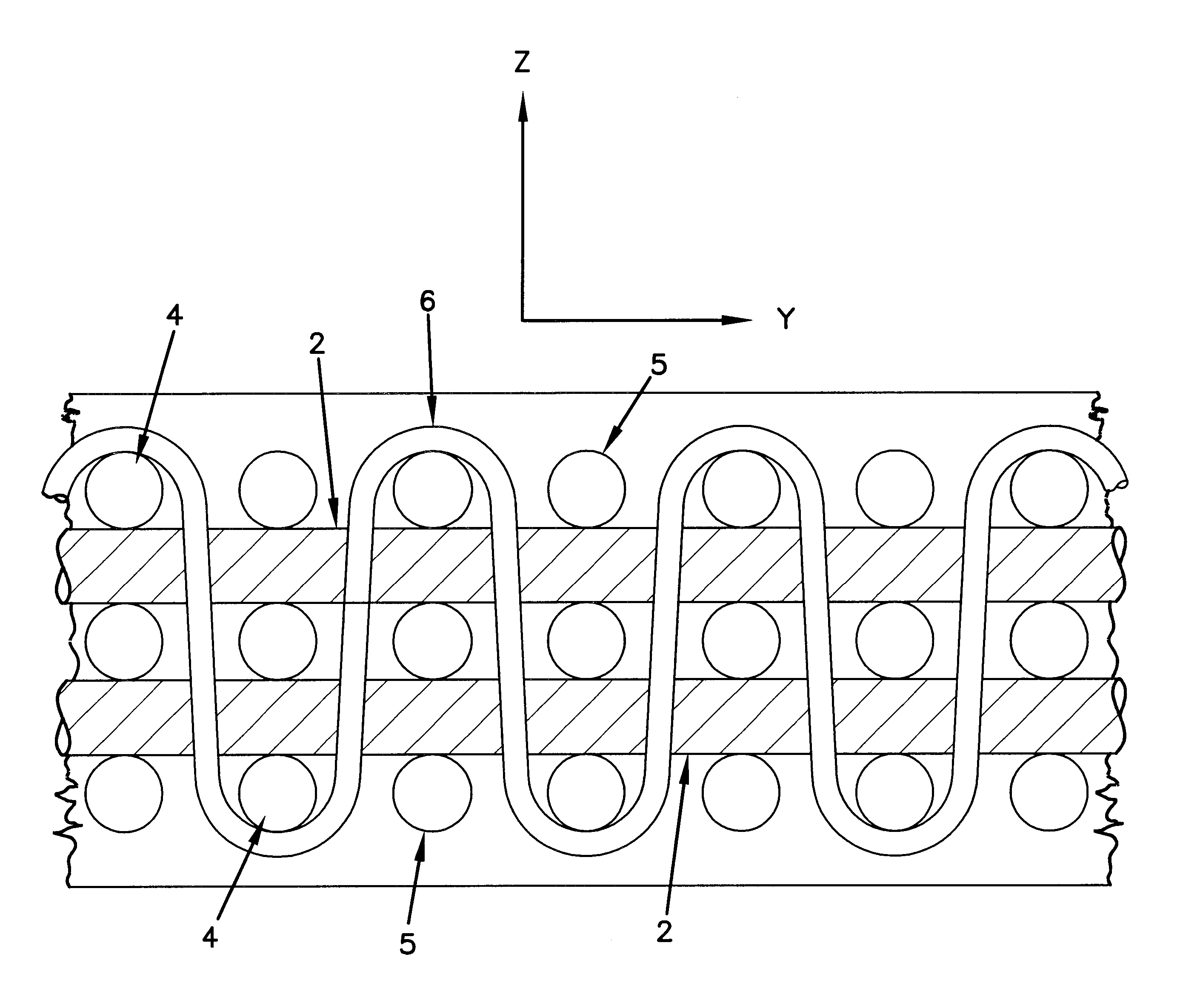
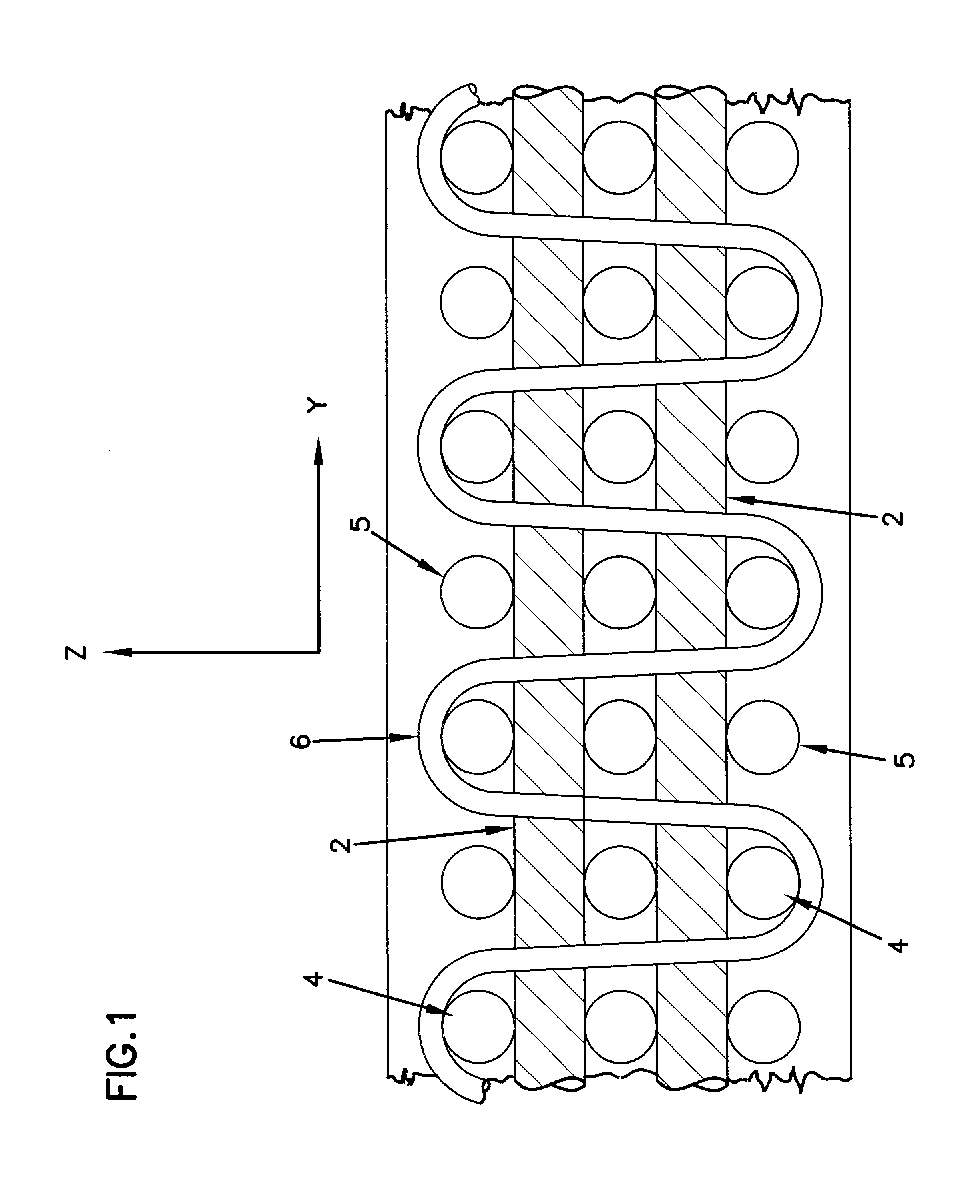
FIGS. 14a and 14b and 15a and 15b show cross sections of reinforcement according to the invention with a top layer of main reinforcement 1 and a bottom layer of main reinforcement 2. (As shown e.g. in FIGS. 1-3, there will typically be several layers of main reinforcement, as well as main reinforcement extending both in the plane of the paper and perpendicular thereto, but for the sake of simplicity only the top and bottom layers of main reinforcement are shown in the figures related to this example).

This example shows the effects of subjecting the various plates or plates shown to a momentary high velocity impact from above, e.g. by means of an explosive as described in Example 4. The pressure imp...


PUM

PropertyMeasurementUnit
Fractionaaaaaaaaaa
Fractionaaaaaaaaaa
Fractionaaaaaaaaaa

Abstract

A shaped article, at least one domain of which has a three-dimensionally reinforced composite structure comprising of a matrix and a reinforcing system (2, 4, 5, 6), the reinforcing system comprising bodies such as bars, wires, cables, or plates embedded in the matrix and extending three-dimensionally in first (4, 5) second (2) and third (6) dimensions therein, the reinforcing system being tension interlocked in at least one dimension in that reinforcement components extending in the first and/or second dimension are tension interlocked to reinforcement components extending in the same dimension(s), but at a transverse distance therefrom, by transverse reinforcement components extending in a dimension transverse, to a plane or surface defined by the reinforcement in the first and/or second dimension. The matrix is preferably a dense cement-based matrix prepared from cement, microsilica, a concrete superplaticiser and water, or a metallic matrix. The shaped articles are capable of absorbing high energy with retention of a substantial degree of internal coherence, e.g. under exposure to high velocity impact.

Description

The present invention relates to a shaped article which is capable of resisting impact, including high velocity impact and other high energy impact.A number of impact challenges, such as attacks with projectiles, shells, grenades, missiles and bombs, have as their main purpose to penetrate and / or damage the objects which they are aimed at. Another class of potentially damaging impact is accidental events such as gas explosions, vehicle (ships, aeroplanes, cars, etc.) collision, impact occurring during earthquakes, and the accidental dropping of articles, e.g. in the offshore industry.Another type of impact is impact processing, such as impact hammering, explosion shaping, etc. Another type of impact occurs in connection with quarrying of stone. For example, large pieces of stone may fall onto trucks or other machinery, and high energy impacts of this type can cause extensive damage.Impact challenges also occur in the form of high energy impact from e.g. explosives. For example, bank...

Claims


Application Information

Patent Timeline
IPC IPC(8): B32B5/16E04C5/01E04H9/10E04C5/07E04C5/06E04H9/04
CPCB32B5/16E04C5/012E04C5/0636E04C5/073E04H9/10E04C5/064Y10T428/25
Inventor BACHE, HANS HENRIK
Owner COMPOSHIELD
Why Eureka
Try Eureka