
Exchange coupling film and magnetoresistance effect type element using this exchange coupling film, and thin film magnetic head using the magnetoresistance effect type element

a technology of exchange coupling film and effect type element, which is applied in the field of exchange coupling film and magnetoresistance effect type element using this exchange coupling film, and the use of thin film magnetic head using the magnetoresistance effect type element, etc., can solve the problems of low corrosion resistance, quenching of the exchange anisotropic magnetic field, and film of fe-mn alloy drawbacks

Inactive Publication Date: 2002-05-14
ALPS ALPINE CO LTD
View PDF7 Cites 44 Cited by
  • Summary
  • Abstract
  • Description
  • Claims
  • Application Information

AI Technical Summary

Benefits of technology

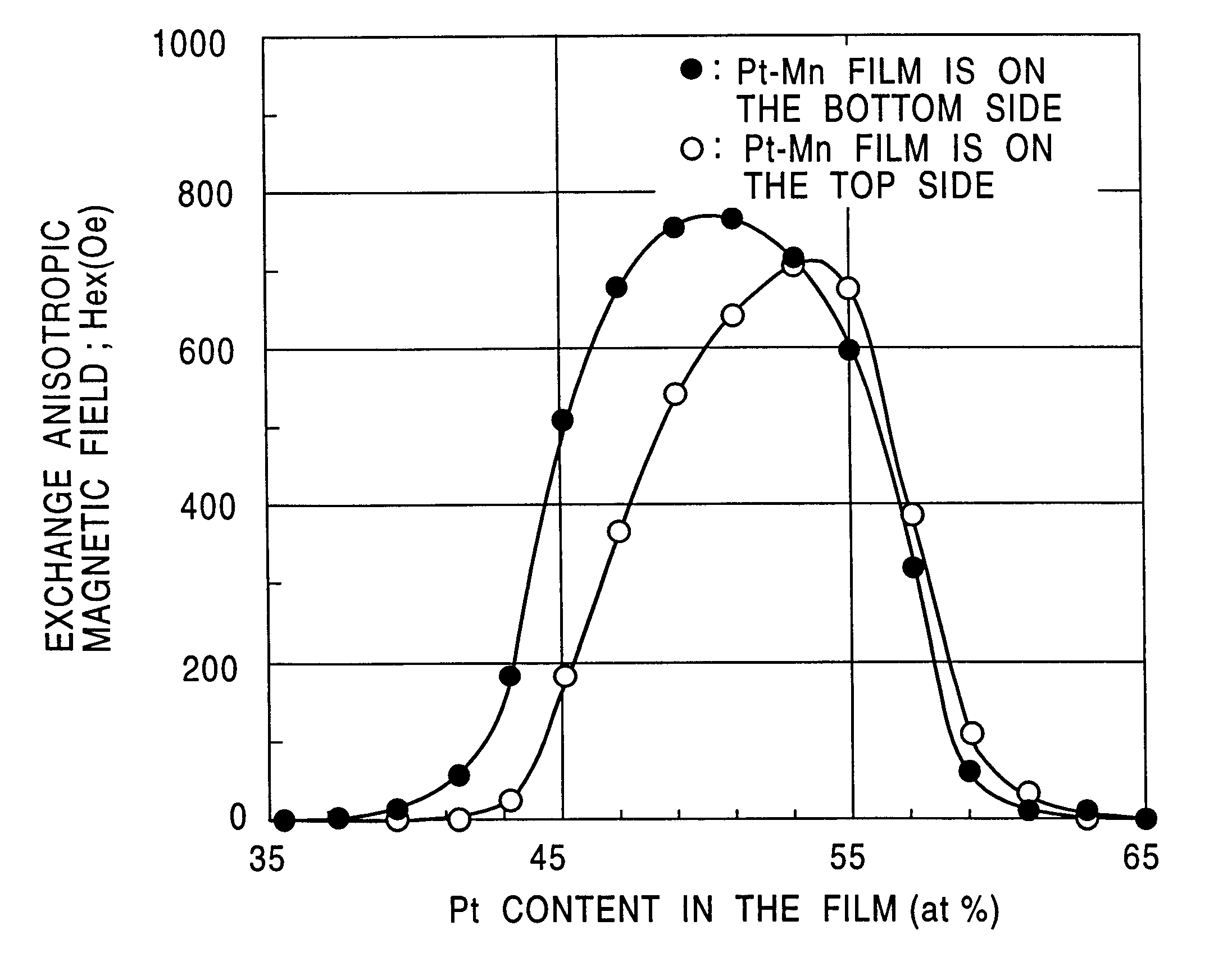
As hitherto described, the interface between the antiferromagnetic layer and ferromagnetic layer is made to be non-coherent by virtue of a proper selection of the composition ratio of the element X in using the X--Mn alloy (X is, for example, Pt or Pd) as an antiferromagnetic layer. However, the lattice constant of the antiferromagnetic layer can be enlarged by allowing an element X' such as a rare gas element (for example Ne or Ar) to contain in the X--Mn alloy in the present invention, making it possible to set the interface structure between the antiferromagnetic layer and ferromagnetic layer to be non-coherent.
Accordingly, the degree of orientation of the {111} plane of the X--Mn alloy or X--Mn--X' alloy is properly controlled to be smaller than the degree of orientation of the ferromagnetic layer or to be non-oriented when, for example, the {111} plane of the ferromagnetic layer is preferentially oriented along the direction parallel to the interface between the antiferromagnetic layer and the X--Mn alloy or X--Mn--X' alloy, thereby making it possible to keep the non-coherency of the interface structure.
The X--Mn alloy (X=Pt, Pd and the like) or X--Mn--X' alloy (X=Ne, Ar and the like) has excellent characteristics as an antiferromagnetic material with respect to superior corrosion resistance to the FeMn alloy or NiMn alloy as well as higher blocking temperature and larger exchange anisotropic magnetic field (Hex) than the FeMn alloy.
The construction described above enables to tightly fix magnetization of the pinned magnetic layer along the prescribed direction, making it possible to obtain good reproduction characteristics as compared with the conventional elements.
The construction above makes it possible to properly aligned the magnetization of the free magnetic layer and magnetoresistive layer, thus making it possible to realize good reproduction characteristics.

Problems solved by technology

Although the films of the Fe--Mn alloy or Ni--Mn alloys are used for the antiferromagnetic layer as described above, the film of the Fe--Mn alloy has drawbacks of low corrosion resistance, small exchange anisotropic magnetic field and a blocking temperature as low as about 150.degree. C.
Low blocking temperature causes a problem that the exchange anisotropic magnetic field is quenched by the temperature increase of the element during the manufacturing process of the head or in the head under operation.
However, the alloy is not sufficient with respect to corrosion resistance as in the FeMn alloys.
Although both of the crystal structure of the X--Mn alloy in the deposition step (before the heat treatment) and the crystal structure of the ferromagnetic layer assumes a face-centered tetragonal lattice (referred to a disordered lattice hereinafter) in which X and Mn atoms are distributed at random, the interface structure between the X--Mn alloy in the deposition step (before the heat treatment) and ferromagnetic layer are liable to be non-coherent since the difference between the lattice constant of the X--Mn alloy and the lattice constant of the ferromagnetic layer are adjusted to be large in the present invention as described previously.
In other words, the crystal structure of the antiferromagnetic layer 4 could be hardly transformed from the disordered lattice to the ordered lattice as a result of applying a heat treatment when the interface structure is coherent, causing a problem that exchange anisotropic magnetic field can not be obtained.
However, it is preferable to transform a part of the crystal structure is transformed into the ordered lattice since a problem of adhesion is caused when all the crystal structure is transformed into the ordered structure.

Method used


Image

  • Exchange coupling film and magnetoresistance effect type element using this exchange coupling film, and thin film magnetic head using the magnetoresistance effect type element
  • Exchange coupling film and magnetoresistance effect type element using this exchange coupling film, and thin film magnetic head using the magnetoresistance effect type element
  • Exchange coupling film and magnetoresistance effect type element using this exchange coupling film, and thin film magnetic head using the magnetoresistance effect type element

Examples


Embodiment Construction

Firstly, a multilayer composed of the film construction described below was deposited in the present invention to investigate the relation between the Pt content as one element constituting the antiferromagnetic layer and the lattice constant of the antiferromagnetic layer.

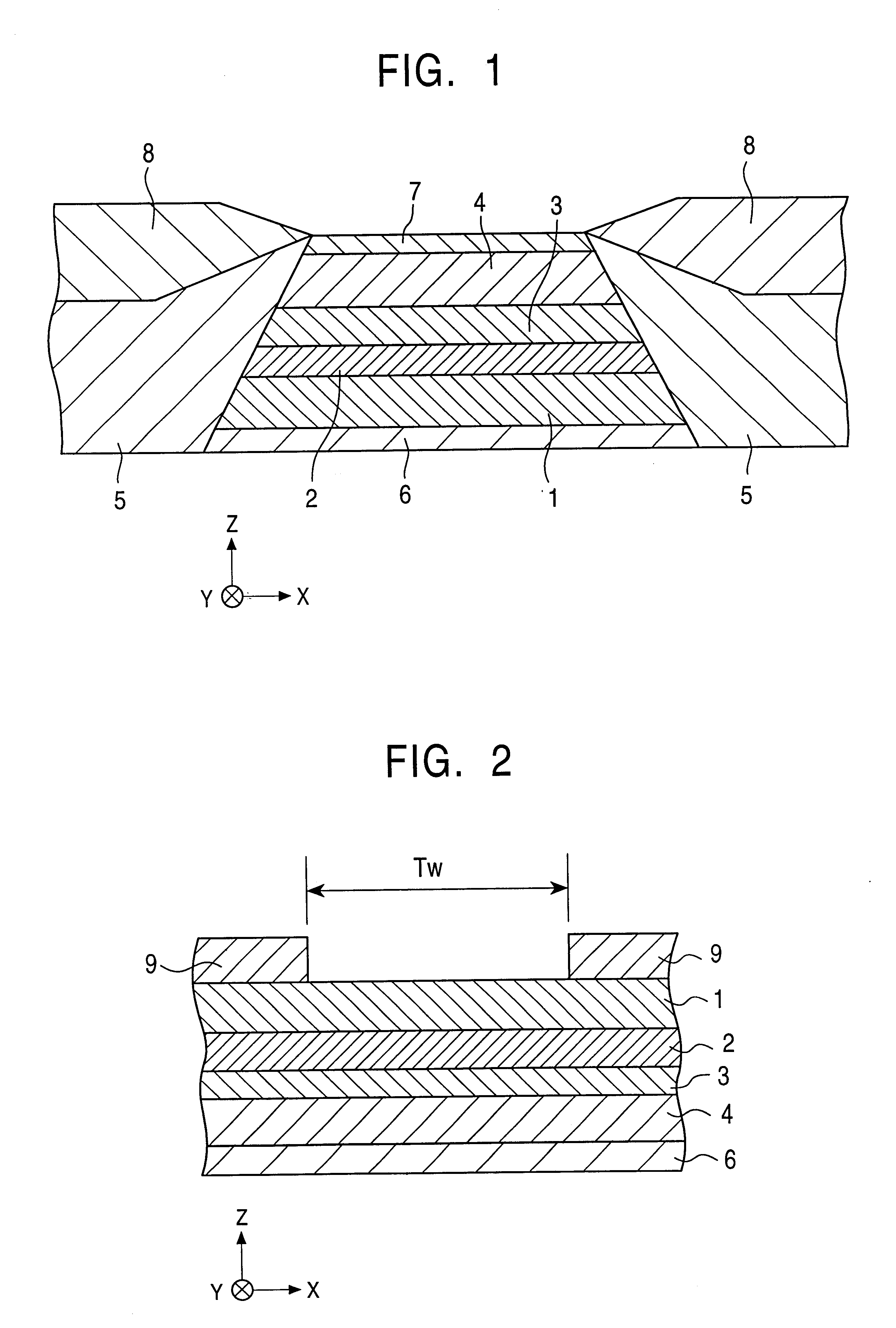
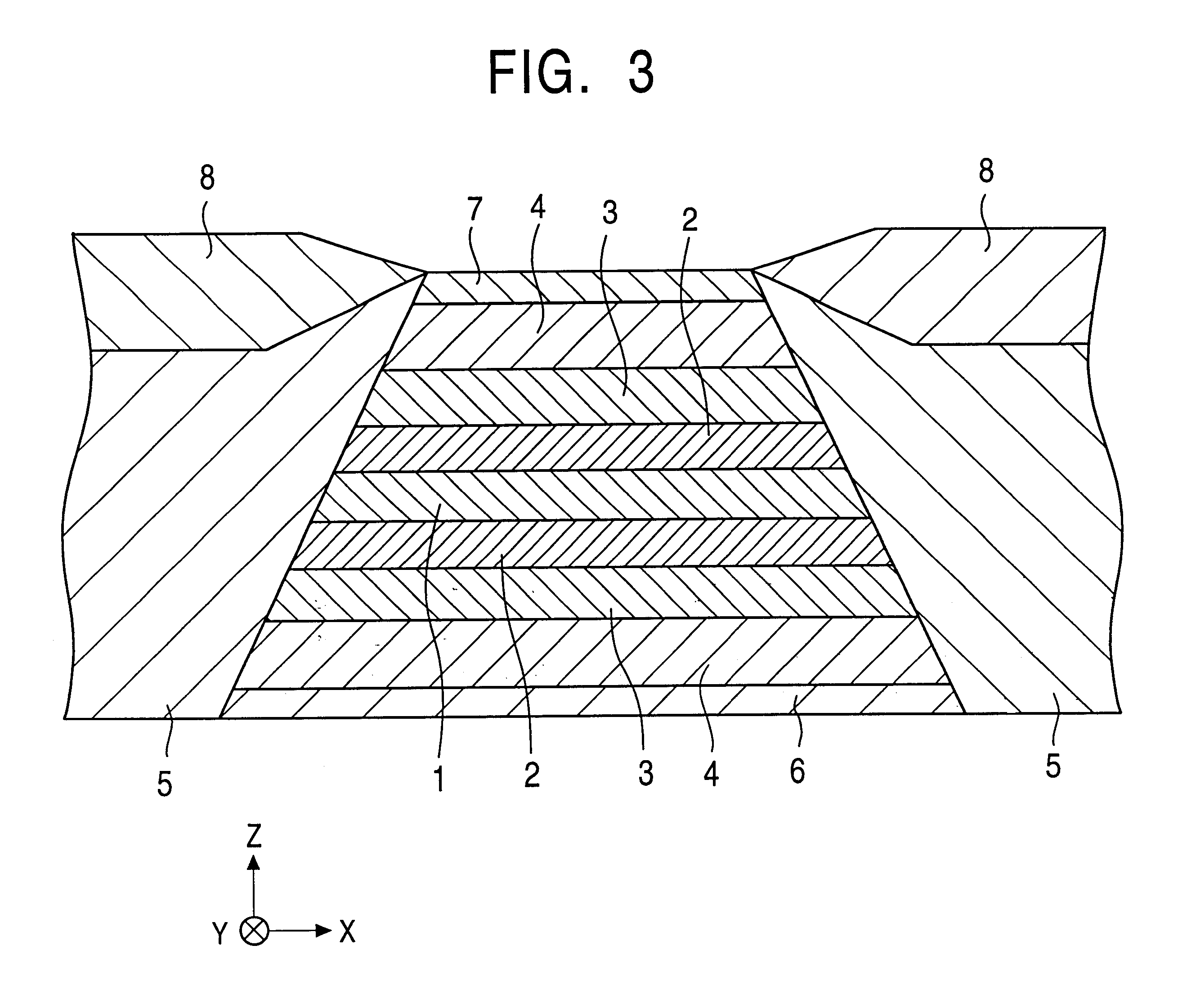
The film was deposited, from the bottom to the top, in the order of; Si substrate / alumina / underlayer: Ta (100) / pinned magnetic layer: NiFe (300) / antiferromagnetic layer: PtMn (300) / Ta (100). The numerals in the parentheses represents the film thickness with Angstrom unit (.ANG.).

The relation between the Pt content and lattice constant of the antiferromagnetic layer was experimentally determined before subjecting to a heat treatment from the peak position in the diffraction pattern by the X-ray diffraction .theta. / 2.theta. method.

It is clear from FIG. 6 that the lattice constant of the antiferromagnetic layer (PtMn layer) becomes large as the Pt content is increased. The lattice constant of the NiFe alloy, CoFe all...


PUM


Abstract

The antiferromagnetic layer 4 is formed of the X-Mn alloy (X is an platinum group element) and the interface structure of with the pinned magnetic layer 3 is made to be non-coherent by properly adjusting the composition ratio of X. Consequently, the crystal structure of the antiferromagnetic layer 4 is transformed so as to obtain a large exchange anisotropic magnetic field by subjecting the layer to a heat treatment, making it possible to improve the reproduction characteristic over the conventional art.

Description

1. Field of the InventionThe present invention relates to an exchange coupling film composed of an antiferromagnetic layer and a ferromagnetic layer, the magnetization direction of the antiferromagnetic layer being fixed along a prescribed direction due to an exchange anisotropic magnetic field generated at the interface between the antiferromagnetic layer and ferromagnetic layer. Especially, the present invention relates to an exchange coupling film being allowed to obtain a larger exchange anisotropic magnetic field when the antiferromagnetic layer is formed of an antiferromagnetic material containing an element X (for example, Pt or Pd) and Mn, and to a magnetoresistive element (spin-valve type thin film element; AMR (anisotropic magnetoresistive) element) using this exchange coupling film.2. Description of the Related ArtThe spin-valve type thin film element belongs to one of GMR (giant magnetoresistive) elements making use of a giant magnetoresistance effect for sensing recordi...

Claims


Application Information

Patent Timeline
IPC IPC(8): G01R33/06G01R33/09G11B5/39H01F10/32H01L43/00H01F10/00H01L43/10H01F10/30H01L43/08
CPCB82Y10/00B82Y25/00G01R33/093G11B5/3903G11B5/3932H01F10/3268H01L43/10H01F10/123Y10T428/1121Y10S428/90G11B2005/3996H10N50/85H01F10/12G11B5/3906
Inventor HASEGAWA, NAOYASAITO, MASAMICHIOOMINATO, KAZUYAYAMAMOTO, YUTAKAMAKINO, AKIHIRO
Owner ALPS ALPINE CO LTD
Learn More