Pulse mode electron generator

a generator and pulse mode technology, applied in the manufacture of electric discharge tubes/lamps, particle separator tubes details, instruments, etc., can solve the problems of difficult to produce electrical pulses of high amplitude and short duration, and the power required is not negligible, so as to facilitate cathode control and reduce power consumption in pulse mode , the effect of facilitating the control of the cathod

Inactive Publication Date: 2002-05-14
ALCATEL LUCENT SAS
View PDF6 Cites 14 Cited by
  • Summary
  • Abstract
  • Description
  • Claims
  • Application Information

AI Technical Summary

Benefits of technology

The present invention addresses the problem of designing a new pulse mode electron generator with a field emission cathode that significantly reduces power consumption in pulse mode and significantly facilitates control of the cathode by an electrical pulse generator that is easier to implement.

Problems solved by technology

It is difficult to produce electrical pulses of high amplitude and short duration and, because of the consumption of electrical energy in the capacitive component that the field emission cathode itself constitutes and whose plates are the grid and the substrate with the micropoints, the power required is not negligible.

Method used


Image

  • Pulse mode electron generator
  • Pulse mode electron generator
  • Pulse mode electron generator

Examples


Embodiment Construction

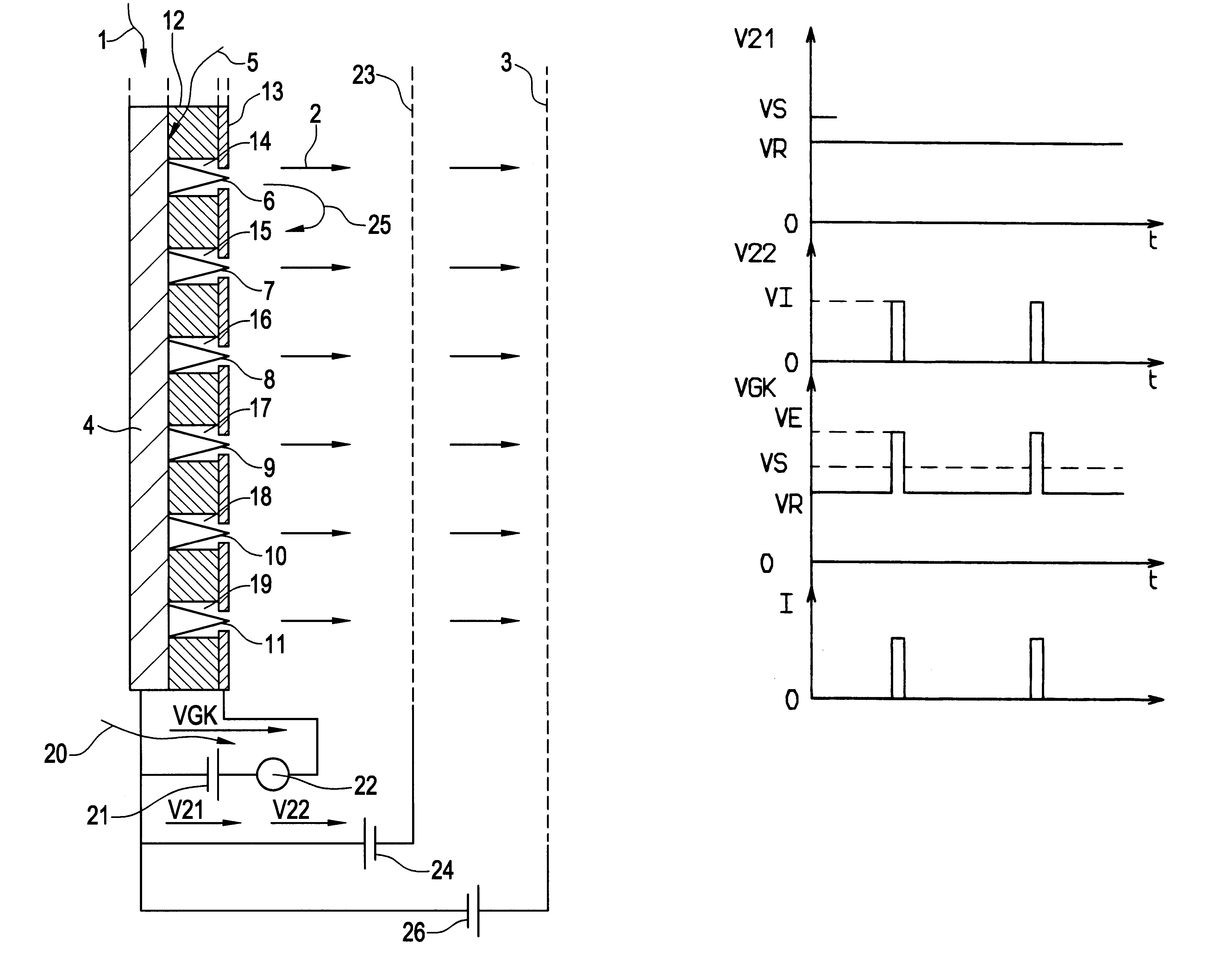
Referring to FIG. 1, a pulse mode electron generator of the present invention includes a field emission cathode 1 to generate a flow 2 of electrons biased by an anode bias generator 26.

The field emission cathode 1 conventionally includes a conductive substrate 4, for example a silicon substrate, having an active face 5 on which micropoints 6-11 are disposed. The active face 5 is covered with an insulative layer 12, for example a silicon oxide layer, separating it from a conductive grid 13. The micropoints 6-11 occupy respective cavities 14-19 in the insulative layer 12 and communicating towards the anode 3 via corresponding openings in the grid 13. The tips of the micropoints 6-11 are flush with the surface of the grid 13.

The height and width of the cavities 14-19, and therefore the height and width of the micropoints 6-11, are of the order of one micron. Arrays of micropoints are generally formed at a density in the order of 10 000 to 100 000 micropoints per mm.sup.2.
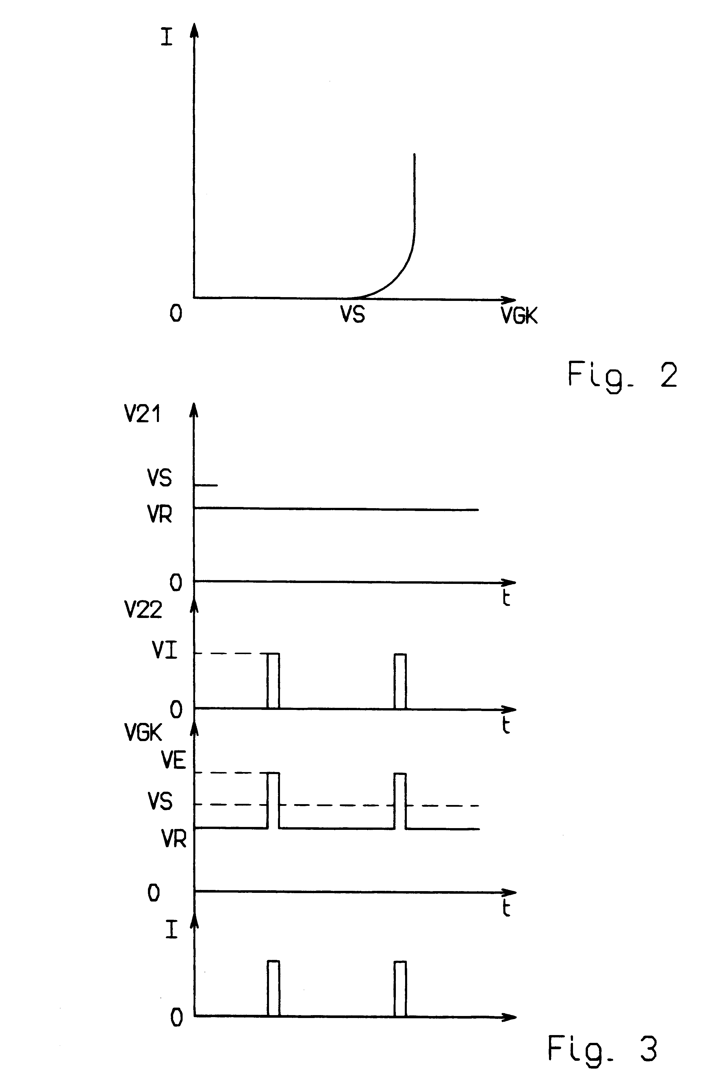
Means 20 for p...


PUM

PropertyMeasurementUnit
bias voltageaaaaaaaaaa
threshold voltageaaaaaaaaaa
temperatureaaaaaaaaaa

Abstract

The pulse mode electron generator of the invention includes a field emission cathode with electron-emitting micropoints associated with a grid biased by means for positively biasing the grid and an anode attracting electrons emitted by the cathode. The grid is biased by a permanent positive pre-bias voltage generator delivering a rest voltage which is slightly lower than the emission threshold voltage of the cathode and in series with a positive pulse voltage generator delivering a pulse component of sufficient value to exceed the emission threshold voltage of the cathode. This facilitates the pulse mode production of electrons and reduces the power consumption needed to produce the electrons.

Description

The present invention relates to electron generators including a field emission cathode with electron-emitting micropoints associated with a grid biased by positive grid biasing means and an anode attracting electrons emitted by the cathode.Field emission cathodes with electron-emitting micropoints were developed as electron generators a few years ago. The electrically conductive micropoints are formed on an appropriate conductive substrate and in cavities of an insulative layer covering the substrate, with their ends flush with a positively biased grid incorporating openings facing each cavity. The sharp tips of the micropoints produce local amplification of the electric field which encourages emission of electrons at room temperature from a threshold voltage in the order of 50 to 100 volts, depending on the construction of the array of micropoints.Field emission cathodes of the above kind have good energy efficiency, better than that of a conventional source of electrons in the fo...

Claims


Application Information

Patent Timeline
Patent Type & Authority Patents(United States)
IPC IPC(8): G09G3/22H01J49/10H01J3/02H01J37/06H01J3/00H01J37/073G01N27/62G01N27/64H01J19/24H01J21/06H01J37/04
CPCG09G3/22H01J49/10H01J37/073H01J3/022
Inventor PIERREJEAN, DIDIER
Owner ALCATEL LUCENT SAS
Why Eureka
Try Eureka