Structures and methods of anti-fuse formation in SOI

a technology of structure and method, applied in the direction of semiconductor devices, semiconductor/solid-state device details, electrical apparatus, etc., can solve the problems of increasing the likelihood of malformation of some portion of the integrated circuit during manufacture, fuses and anti-fuses require significant chip space, and the placement of an increasing number of elements in a complex circuit is often difficul

Inactive Publication Date: 2002-05-28
IBM CORP
View PDF16 Cites 73 Cited by
  • Summary
  • Abstract
  • Description
  • Claims
  • Application Information

AI Technical Summary

Benefits of technology

It is another object of the invention to provide an anti-fuse structure having low programming voltage and current and reduced thermal effect on surrounding elements.
It is a further object of the invention to provide an anti-fuse structure which is electrically and thermally isolated from the active device layer of an SOI substrate to avoid compromise of active devices and / or to increase the reliability of an integrated circuit formed therein.

Problems solved by technology

As integrated circuit complexity increases, however, the likelihood of a malformation of some portion of the integrated circuit during manufacture increases as well.
This fact is becoming more critical at increased integration densities and reduced operating and breakdown voltages due to the potential for damage to other circuit elements since excessive heat voltage and / or current alone or in combination can damage device structures that are becoming more critical with improved performance.
Additionally, fuses and anti-fuses require significant chip space (including separations to limit thermal effects) and placement among complex circuits of increased numbers of elements is often difficult.
Further, since the SOI structure is of substantial cost relative to other structure providing lower active device performance, the cost of forming fuses and anti-fuses in terms of the cost of their respective "footprints" is substantial.

Method used


Image

  • Structures and methods of anti-fuse formation in SOI
  • Structures and methods of anti-fuse formation in SOI
  • Structures and methods of anti-fuse formation in SOI

Examples


first embodiment

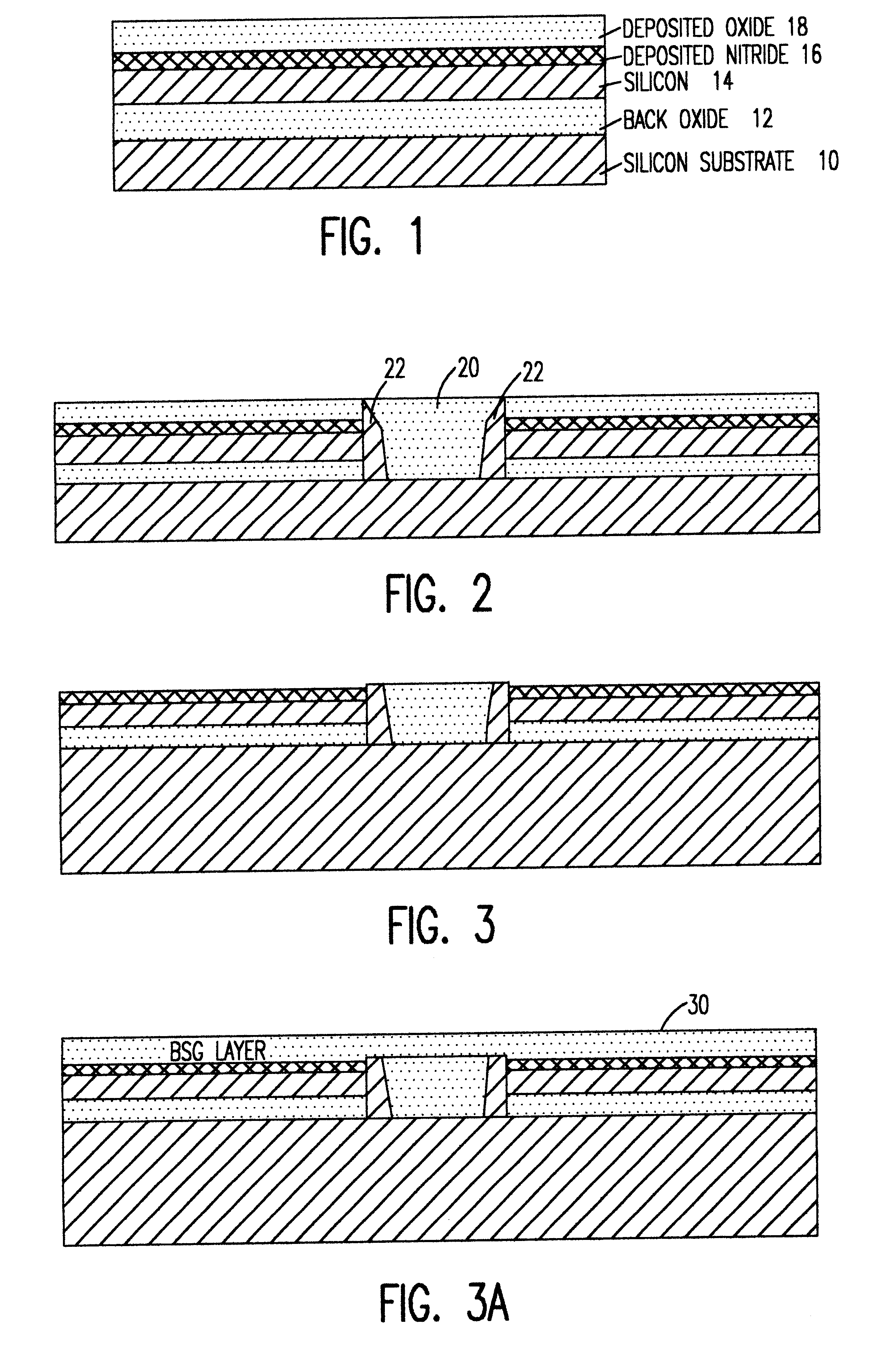
Referring now to the drawings, and more particularly to FIG. 1, there is shown, in cross-sectional view, a starting wafer for formation of an anti-fuse in accordance with the invention. As is characteristic of silicon-on-insulator (SOI) wafers, a relatively thick bulk silicon layer 10 is provided to provide mechanical robustness and facilitate handling and to provide an electrically conductive ground plane. For purposes of the practice of the invention, however, this bulk silicon is preferably formed or treated (e.g. implanted) to include dopants that regulate the bulk resistance to a desired value, as will be discussed in greater detail below. The bulk silicon is covered with an insulator 12, generally an oxide (and thus referred to as a back oxide or BOX), and the insulator is covered by a thin monocrystalline silicon layer 14 of extremely high quality, often referred to an active device layer.

It should be understood that, while the invention will be described in terms of a SOI wa...

second embodiment

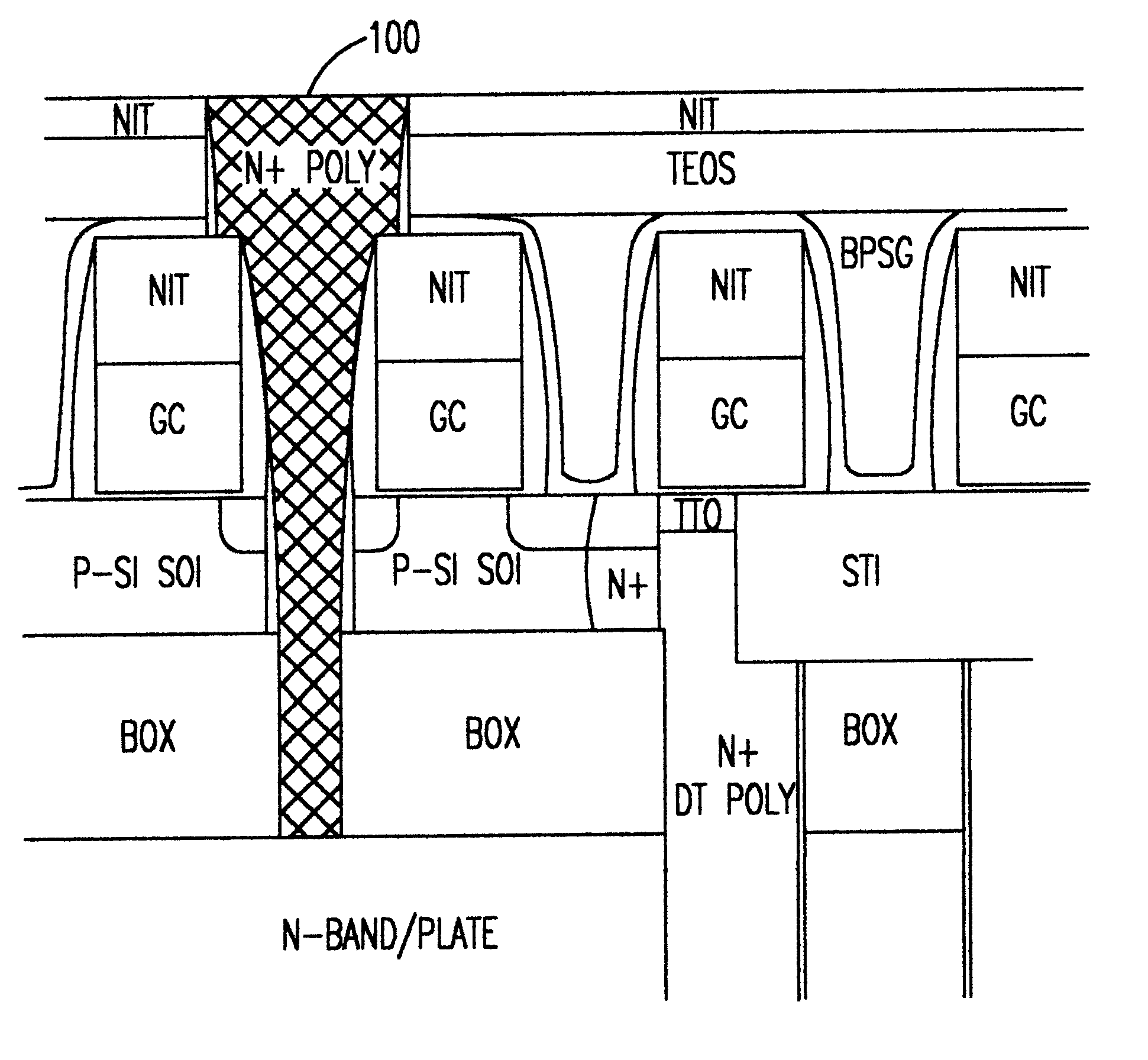
This structure may be used in several ways. If suitable isolation is provided, the capacitor 70 can be read as a two terminal device. The connection can also be used to repair, for example, bit lines or to connect redundant devices to replace marginal or inoperative devices. Further, since both electrodes of the capacitor are available, the capacitor dielectric can be damaged by an overvoltage to program the anti-fuse. Other uses and ancillary structure to accommodate them will be evident to those skilled in the art in view of the present disclosure. In any event, the connection in accordance with this second embodiment of the invention is potentially of a size which can be placed at any location in an integrated circuit including features spaced at minimum lithographic feature size and can be formed at any stage of manufacture of the integrated circuit that includes the devices or structures between which it is to be placed.

Therefore, the second embodiment of the invention is fully...


PUM


Abstract

An anti-fuse structure that can be programmed at low voltage and current and which potentially consumes very little chip spaces and can be formed interstitially between elements spaced by a minimum lithographic feature size is formed on a composite substrate such as a silicon-on-insulator wafer by etching a contact through an insulator to a support semiconductor layer, preferably in combination with formation of a capacitor-like structure reaching to or into the support layer. The anti-fuse may be programmed either by the selected location of conductor formation and / or damaging a dielectric of the capacitor-like structure. An insulating collar is used to surround a portion of either the conductor or the capacitor-like structure to confine damage to the desired location. Heating effects voltage and noise due to programming currents are effectively isolated to the bulk silicon layer, permitting programming during normal operation of the device. Thus the potential for self-repair without interruption of operation is realized.

Description

1. Field of the InventionThe present invention generally relates to increasing manufacturing yield of integrated circuit devices and, more particularly, to the formation of various anti-fuse structures in the bulk semiconductor substrate of silicon on insulator (SOI) wafers and similar layered substrates.2. Description of the Prior ArtThe advantages of increased functionality and performance of integrated circuit devices and increased economy of manufacture derived from increased integration density have led to substantial advances in lithography and other manufacturing processes that allow reduction of sizes of transistors, capacitors and other electronic circuit elements and substantial increases in integrated circuit complexity. As integrated circuit complexity increases, however, the likelihood of a malformation of some portion of the integrated circuit during manufacture increases as well. Therefore, it has been a common incident of integrated circuit design to provide for repa...

Claims


Application Information

Patent Timeline
Patent Type & Authority Patents(United States)
IPC IPC(8): H01L23/52H01L23/525H01L27/108H01L21/02H01L21/334H01L27/12H01L21/82
CPCH01L23/5252H01L27/10897H01L27/10829H01L27/1203H01L29/66181H01L2924/0002H01L2924/3011H01L2924/00H10B12/37H10B12/50H01L27/02
Inventor BERTIN, CLAUDE L.DIVAKARUNI, RAMACHANDRAHOUGHTON, RUSSELL J.MANDELMAN, JACK A.TONTI, WILLIAM R.
Owner IBM CORP
Why Eureka
Try Eureka