Alternator

a technology of alternators and motors, applied in the field of alternators, can solve the problems of fan noise and magnetic noise in particular, noise from automotive alternators, and has remained a problem, and achieve the effect of satisfying performance and quality, and high serviceability and productivity

Inactive Publication Date: 2002-05-28
MITSUBISHI ELECTRIC CORP
View PDF14 Cites 39 Cited by
  • Summary
  • Abstract
  • Description
  • Claims
  • Application Information

AI Technical Summary

Benefits of technology

The present invention aims to solve the above problems with the conventional art and an object of the present invention is to provide an alternator having both high serviceability and productivity, capable of satisfying the performance and quality commonly required of today's alternators.
An additional object of the present invention is to provide an alternator applicable to automotive use which has compactness, high output, and low noise.

Problems solved by technology

Furthermore, there is increased need for noise reduction both inside and outside automotive vehicles, and although engine noise has been reduced, noise from automotive alternators, which run constantly to generate electricity in order to supply the electrical load for the vehicle, has remained a problem.
Fan noise and magnetic noise in particular have been problems in automotive alternators which operate in a wide range of rotational frequencies from low to high speed.
Because automotive alternators are constantly generating electricity, they generate a lot of heat due to the joule heat of the output electric current and are subjected to a severe heat environment, requiring extremely high heat resistance.
Furthermore, within the engine compartment, an automotive alternator is often mounted directly onto an engine, where it is exposed to liquids such as engine oil and antifreeze, in addition to rain water, salt water, mud, etc., conditions where the corrosive environment is extremely severe.
There are problems due to corrosion which lead to interruptions in power generation, etc., but most causes of interruption to power generation are the result of damage to insulation on a winding which occurs during the process of manufacturing a stator, or due to electrical short-circuiting in structurally exposed portions of the winding.
Thus, because the front-end coil end group is constructed by circumferentially arranging the joint portions formed by joining the end portions 54b, which have lost their insulation due to soldering or welding, the coil-end construction is easily corroded by exposure to moisture, making corrosion resistance extremely low.
Furthermore, because the front-end coil end group is composed of two rows of ninety-six joint portions, i.e., 192 joint portions, the construction facilitates short-circuiting between the joint portions, increasing the likelihood of short-circuiting accidents.
Furthermore, the amount of each conductor segment 54 which is inserted into the slots 51a must be greater than the length of the stator core 51, facilitating damage to the insulation and reducing the quality of the finished product.
In addition, when joining the end portions 54b, short-circuiting often occurs between the joint portions due to spilt solder or weld melt, significantly decreasing mass-producibility.
As a result, coil leakage reactance in the coil end portions is increased, causing output to deteriorate, and wind resistance is increased, exacerbating wind noise.
However, when attempts are made to adopt this example of improvement of magnetic noise in small stators, the slot spacing becomes extremely narrow because twice as many slots are required.
Thus, it was not possible to apply general winding methods in which a stator winding is constructed by preparing an annular coil by winding continuous wire into an annular shape, then, preparing a star coil by deforming this annular coil into a star shape, then installing straight portions of the star coil into the slots of the stator core.
Now, with the former, the output commencement frequency can be shifted to the low-speed side by increasing the supply of electric current to the field coil, but this is limited by reductions in the saturation of the magnetic circuits.
With the latter, the output commencement frequency can be shifted to the low-speed side by increasing the number of turns, but when attempts are made to increase the total conductor count in a winding based on conductor segments 54, the number of joint portions increases proportionately, leaving no space for joining, and excessive increases in the number of turns cannot be practically applied.

Method used


Image

  • Alternator
  • Alternator
  • Alternator

Examples


embodiment 1

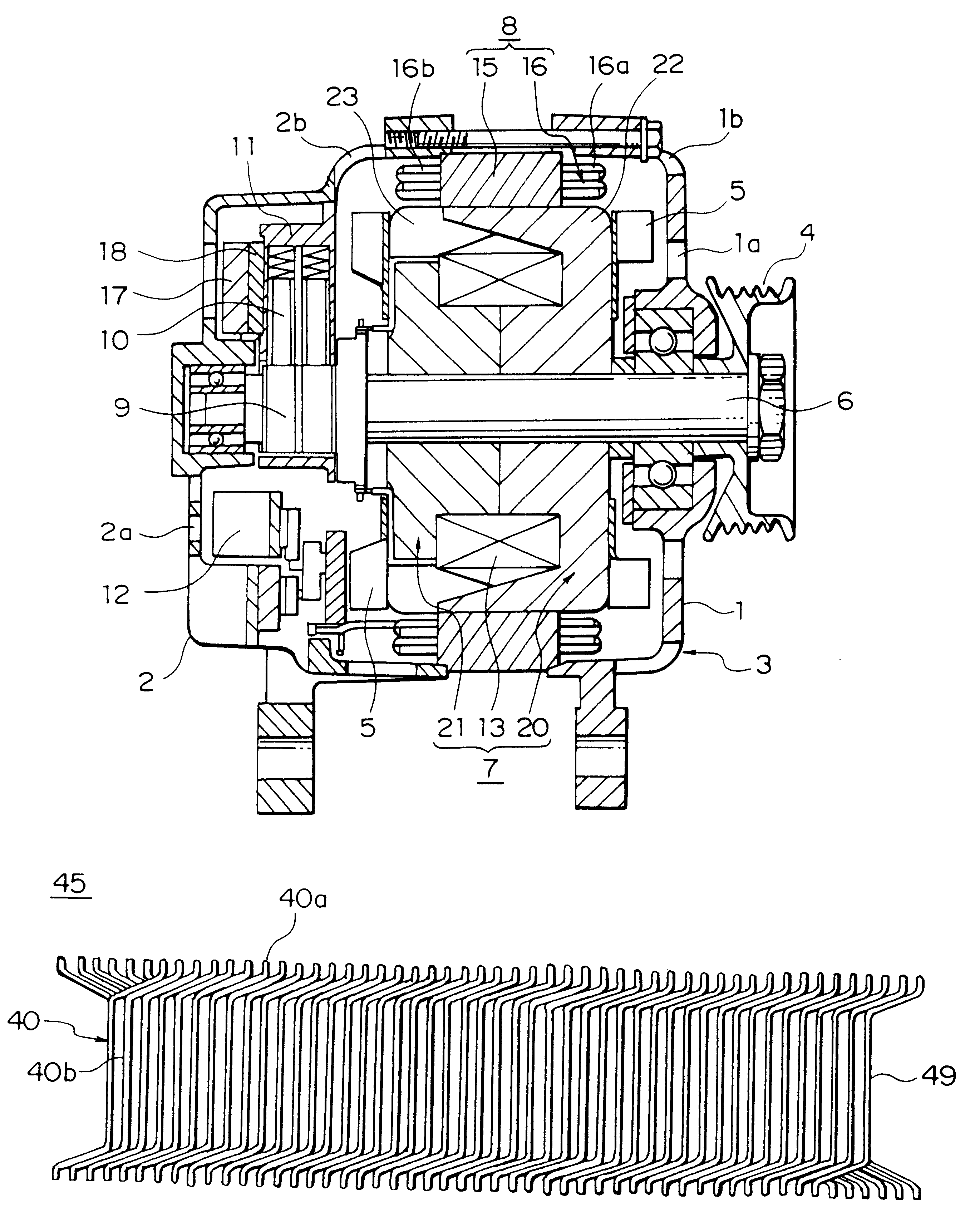
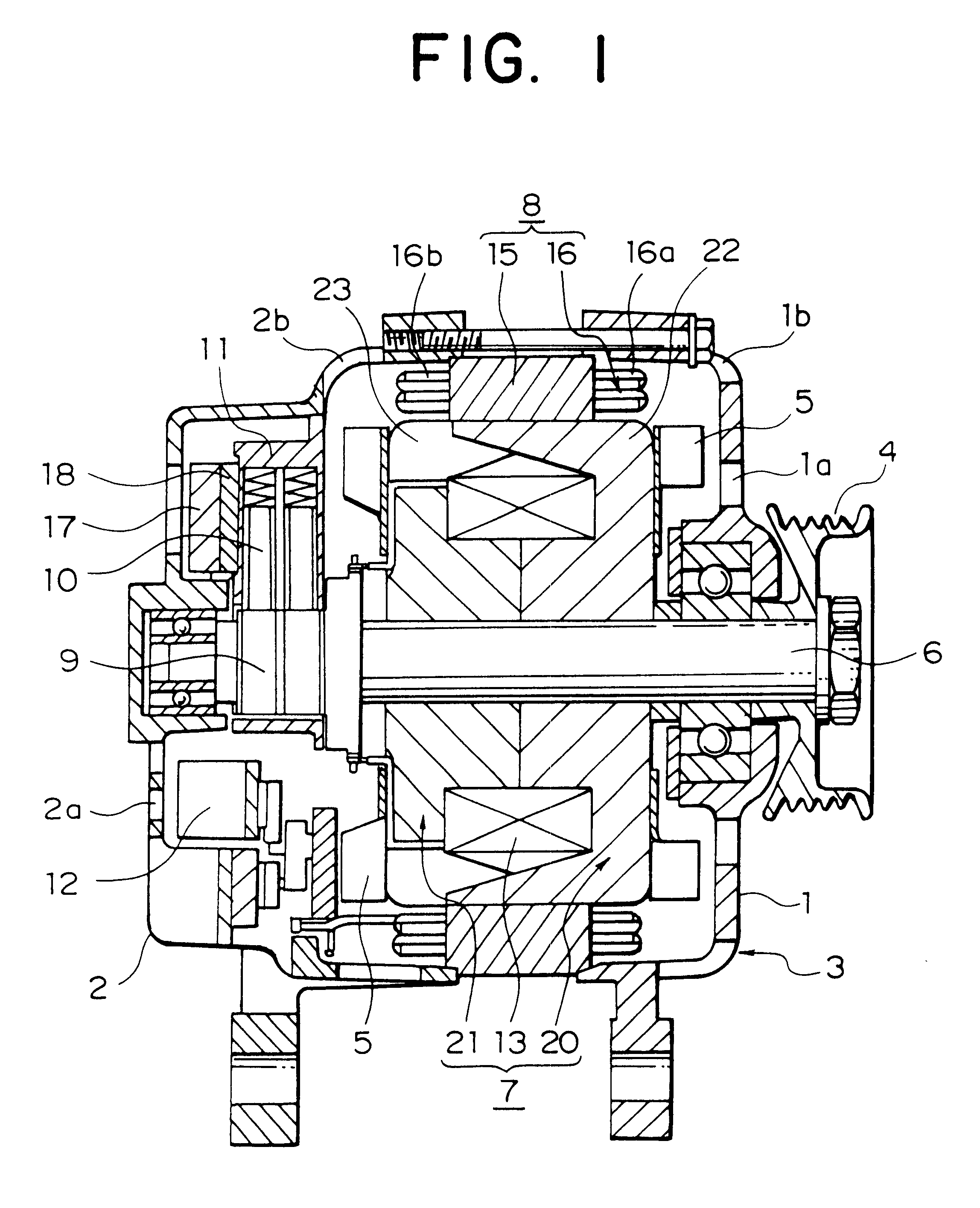
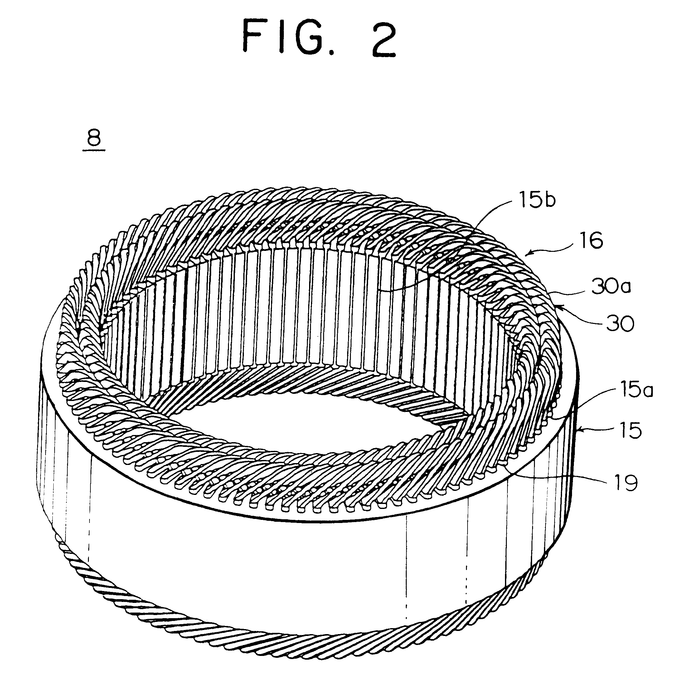
FIG. 1 is a cross section showing a construction of an automotive alternator according to Embodiment 1 of the present invention, FIG. 2 is a perspective showing a stator of this automotive alternator, FIG. 3 is an end elevation explaining connections in one phase of stator winding group in this automotive alternator, FIG. 4 is a circuit diagram for this automotive alternator, FIGS. 5 and 6 are diagrams explaining the manufacturing process for winding groups constituting part of the stator winding used in this automotive alternator, FIGS. 7A and 7B are an end elevation and a plan view, respectively, showing an inner-layer wire-strand group constituting part of the stator winding used in this automotive alternator, FIGS. 8A and 8B are an end elevation and a plan view, respectively, showing an outer-layer wire-strand group constituting part of the stator winding used in this automotive alternator, FIG. 9 is a perspective showing part of a strand of wire constituting part of the stator ...

embodiment 2

FIG. 16 is an end elevation explaining connections in one phase of stator winding group in the automotive alternator according to Embodiment 2 of the present invention.

In FIG. 16, one phase of stator winding group 161A is constituted by first to fourth winding sub-portions 41 to 44 each composed of one strand of wire 40. Copper wire material having a rectangular cross section and covered with an insulative coating 49, for example, is used in the strands of wire 40.

The first winding sub-portion 41 is formed by wave winding one strand of wire 40 into every sixth slot from slot numbers 1 to 91 so as to alternately occupy a first position from an outer circumferential side and a fourth position from the outer circumferential side inside the slots 15a. The second winding sub-portion 42 is formed by wave winding a strand of wire 40 into every sixth slot from slot numbers 1 to 91 so as to alternately occupy the fourth position from the outer circumferential side and the first position from...

embodiment 3

FIG. 23 is a partial cross section showing an automotive alternator according to Embodiment 3 of the present invention, FIG. 24 is a perspective showing a stator used in the automotive alternator according to Embodiment 3 of the present invention, FIG. 25 is a perspective showing part of the rotor used in the automotive alternator according to Embodiment 3 of the present invention, FIG. 26 is a perspective explaining the construction of the rotor used in the automotive alternator according to Embodiment 3 of the present invention, FIG. 27 is a circuit diagram for the automotive alternator according to Embodiment 3 of the present invention, FIGS. 28A and 28B are diagrams explaining the construction of a stator core used in the automotive alternator according to Embodiment 3 of the present invention, FIG. 28A being a side elevation and FIG. 28B being a rear elevation. Moreover, output wires are omitted from FIG. 24.

As shown in FIG. 23, in this alternator, a fan 5 is disposed only on a...


PUM


Abstract

An alternator includes a rotor for forming north-seeking (N) and south-seeking (S) poles about a rotational circumference, a stator having a stator core disposed facing the rotor and a polyphase stator winding installed in the stator core, and a bracket supporting the rotor and the stator, wherein the stator core comprises a laminated iron core formed with a number of slots extending axially at a predetermined pitch in a circumferential direction, the polyphase stator winding comprises a number of winding sub-portions in each which a long strand of wire is wound so as to alternately occupy an inner layer and an outer layer in a slot depth direction within the slots at intervals of a predetermined number of slots, the strand of wire folding back outside the slots at axial end surfaces of the stator core to form turn portions, the turn portions align in a circumferential direction to constitute coil end groups at both axial end portions of the stator core, and the turn portions at both axial end portions of the stator core are provided with an insulative coating.

Description

BACKGROUND OF THE INVENTION1. Field of the InventionThe present invention relates to an alternator driven by an internal combustion engine, for example, and in particular, relates to a stator construction for an automotive alternator mounted to an automotive vehicle such as a passenger car or a truck.2. Description of the Related ArtIn recent years, compact high output and improvements in quality have been increasingly required of alternators. In order to achieve compact high output, it is important to design constructions which distribute magnetic loading and electrical loading in the most appropriate manner, and with the highest possible density within a limited volume.For example, as engine compartments become progressively smaller, mounting space for automotive alternators is becoming less and less free, but at the same time, improvements in alternator output are required because of increases in automotive vehicle loads. Furthermore, there is increased need for noise reduction b...

Claims


Application Information

Patent Timeline
Patent Type & Authority Patents(United States)
IPC IPC(8): H02K3/28H02K3/34H02K9/06H02K3/12H02K1/16H02K3/32H02K3/50H02K9/04H02K15/02H02K15/06H02K15/00H02K15/04H02K3/04H02K3/24H02K3/30H02K19/22
CPCH02K1/16H02K1/165H02K3/12H02K3/28H02K3/345H02K3/50H02K15/024H02K15/0478H02K15/066H02K9/06H02K2203/09H02K3/32
Inventor ASAO, YOSHIHITOADACHI, KATSUMIMORISHITA, AKIRA
Owner MITSUBISHI ELECTRIC CORP
Why Eureka
Try Eureka