Combustion device

a combustion device and combustion technology, applied in the direction of burner control devices, combustion types, combustion using lumps and pulverizing fuel, etc., can solve the problem of insufficient fuel combustion performance during normal combustion

Inactive Publication Date: 2002-06-11
DENSO CORP
View PDF13 Cites 16 Cited by
  • Summary
  • Abstract
  • Description
  • Claims
  • Application Information

AI Technical Summary

Problems solved by technology

However, in the conventional combustion device, since the fuel collision space is provided at the downstream side of the injection nozzle, a wall for defining the fuel collision space restricts fuel from flowing from the injection nozzle to the combustion chamber.
Therefore, fuel may be not distributed in an entire range in the combustion chamber, and fuel combustion performance during a normal combustion becomes insufficient.

Method used


Image

  • Combustion device
  • Combustion device
  • Combustion device

Examples


first embodiment

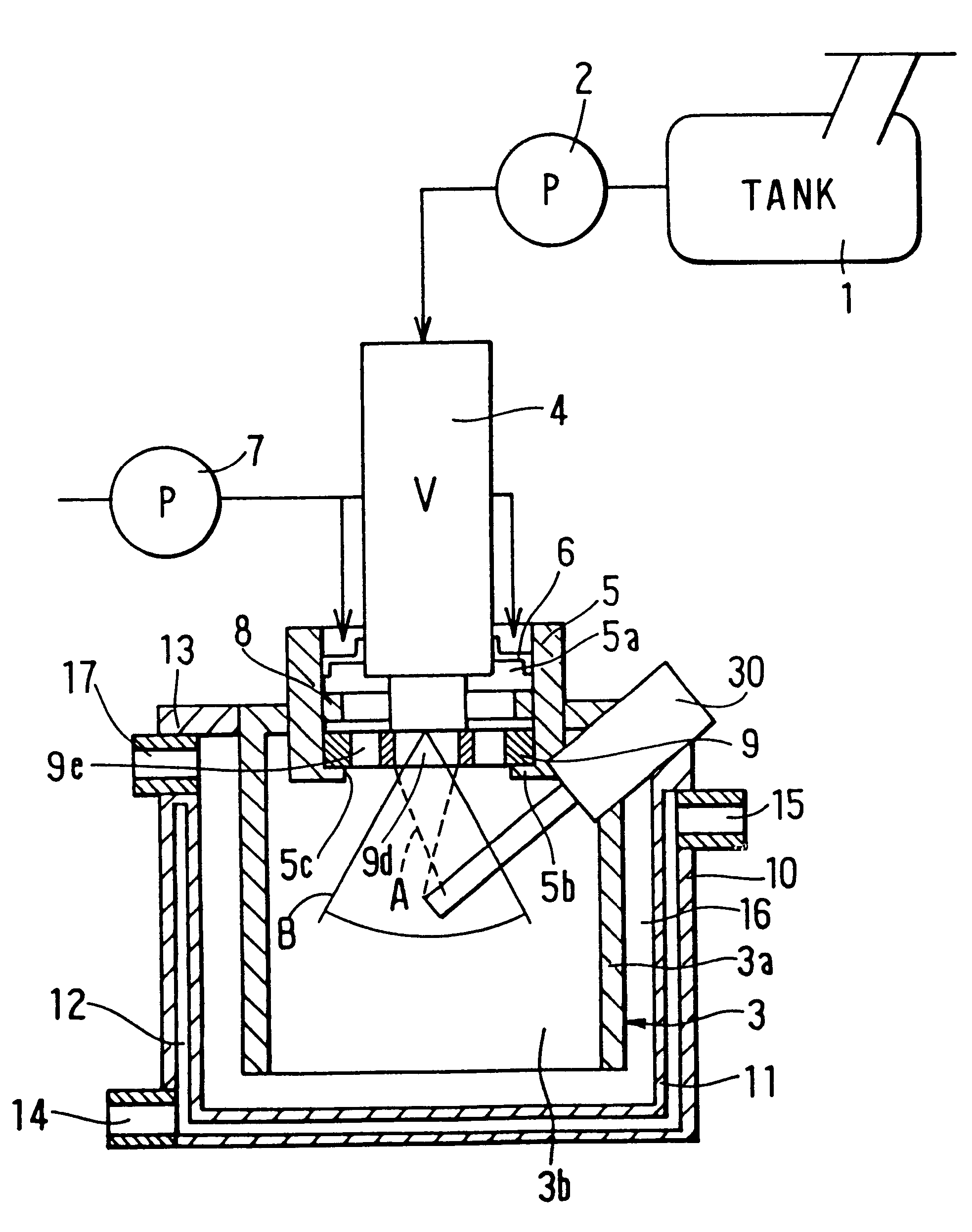
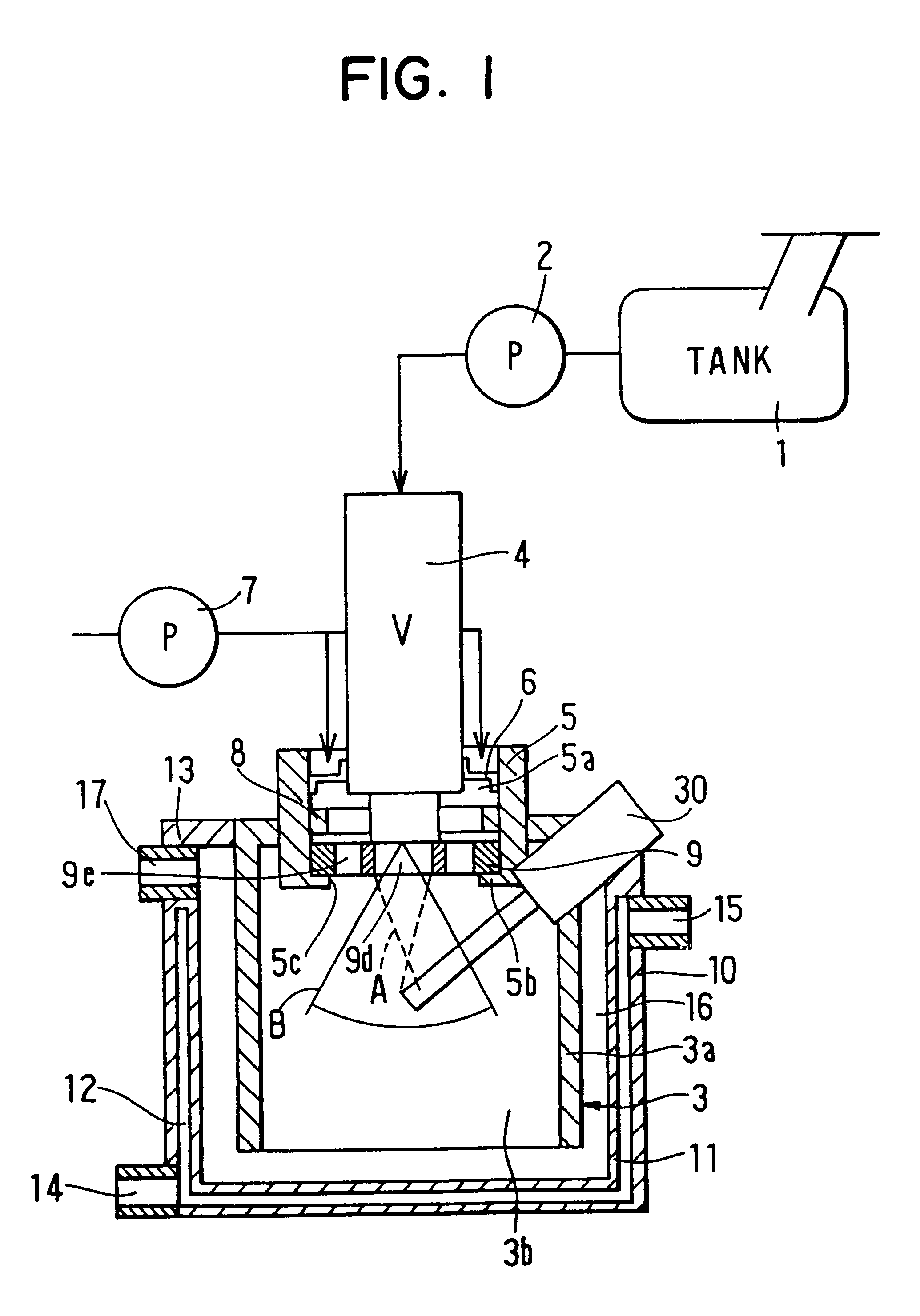
In the first embodiment, four injection ports 27 (see FIG. 6) are provided in the fuel injection valve 4. Further, a diameter of each injection port 27 is set at 0.15 mm, an injection angle .alpha. of fuel is set at 66.degree.. Further, a distance shown by "x" in FIG. 2, between a top end of the fuel injection valve 4 and the injection port 27 in the axial direction is set at 0.3 mm. A diameter of the plate portion 9c of the fuel collision member 9 is 16 mm, a diameter of the fuel-flowing hole 9d is 5 mm, and a distance between the first and second surfaces 9a, 9b (i.e., thickness "y" of the plate portion 9c) is 4.5 mm. Further, the plate portion 9c has a step portion 9g for supporting the fuel injection valve 4. A wall thickness (i.e., thickness "Z" in FIG. 2) of the plate portion 9c at the step portion 9g is 3.55 mm.

In a boundary between an inner wall for defining the fuel-flowing hole 9d of the fuel collision member 9 and the plate portion 9c, edges are formed on the first and se...

second embodiment

In the second embodiment, as shown in FIG. 8, four leg portions 90 are integrally formed with the plate portion 9c of the fuel collision member 9 to have a predetermined distance between adjacent two. Each of the four leg portions 90 has a hole portion 90a at a position corresponding to the flange portion 5b provided inside the cylindrical portion 5. Therefore, the leg portions 90 of the fuel collision member 9 is fixed to the flange portion 5b of the cylindrical portion 5 by screwing screws 40 into the hole portions 90a, as shown in FIGS. 8, 9.

The fuel collision member 9 is made of aluminum having thermal expansion coefficient of 31.times.10.sup.-6 / k. Further, the cylindrical portion 5 is made of nickel chrome steel having thermal expansion coefficient of 12.times.10.sup.-6 / k. Thus, when the temperature within the combustion chamber 3b is 500.degree. C., the leg portion 90 of the fuel collision member 9 are thermal-expanded approximately by 0.2 mm, the plate portion 9c is thermal...

fourth embodiment

A fourth preferred embodiment of the present invention will be now described with reference to FIGS. 12-15. In the fourth embodiment, for selectively switching the collision operation mode and the non-collision operation mode for fuel injected from the fuel injection valve 4, the pressure of air is used.

In the fourth embodiment, at the fuel injection side of the fuel injection valve 4, a valve member 56 is provided. As shown in FIGS. 12, 13A-13C, the valve member 56 includes a coil spring 53, and a valve portion 52 having an opening 50 through which injection fuel passes and four openings 51 through which air from the air pump 7 passes.

Specifically, as shown in FIG. 12, a housing 60 is disposed at the fuel injection side of the fuel injection valve 4 to form an air introduction chamber 71. The housing 60 is attached to the cover portion 70 of the combustion receiver 3. An air pipe 61 is connected to the housing 60 so that an axial line of the air pipe. 61 is crossed with an axial li...


PUM


Abstract

In a combustion unit, a fuel collision member is disposed between a fuel injection valve and a combustion chamber. The fuel collision member is positioned so that, a part of fuel injected from said fuel injection valve is introduced into the combustion chamber while colliding with the fuel collision member, and the other part of fuel is directly introduced into the combustion chamber without colliding with the fuel collision member. Thus, fuel introduced into the combustion chamber is atomized while being introduced into the combustion chamber in a wide range.

Description

This application is related to and claims priority from Japanese Patent Applications No. Hei. 11-41791 filed on Feb. 19, 1999, and No. Hei. 11-309415 filed on Oct. 29, 1999, the contents of which are hereby incorporated by reference.1. Field of the InventionThe present invention relates to a combustion device which is suitably used for a heating unit for heating a passenger compartment of a vehicle or for heating a vehicle component, for example.2. Description of Related ArtIn a conventional combustion device described in JP-A-9-209875, a fuel collision space is provided at a downstream position of an injection nozzle of a fuel injection unit, nozzle holes are provided at positions opposite to the fuel collision space with each other, and fuel injected from the injection nozzle is introduced into the fuel collision space from the nozzle holes to collide with each other in the fuel collision space.Fuel collided in the collision space is pounded to become a minute-particle atomized st...

Claims


Application Information

Patent Timeline
Patent Type & Authority Patents(United States)
IPC IPC(8): F23D11/10F23D11/40F23N5/00B60H1/22F23D7/00F23D11/24F23D11/26F23N1/00
CPCF23D11/10F23D11/402F23N5/006F23C2205/10F23D2208/10F23K2900/05001F23K2900/05003F23N2041/14F23N2025/16F23N2027/36F23N2033/08F23N2035/14F23N2035/28F23N2035/30F23N2225/16F23N2227/36F23N2235/28F23N2235/30F23N2241/14F23N2233/08F23N2235/14
Inventor OKADA, HIROSHIKAWAGUCHI, KIYOSHI
Owner DENSO CORP
Why Eureka
Try Eureka