Interphase device for the direct coupling of liquid chromatography and gas chromatography

a technology of interphase device and liquid chromatography, which is applied in the direction of ion-exchanger, separation process, instruments, etc., can solve the problems of difficult to make two essentially different systems, the interface described up to date in literature has limitations, and the use of relatively high volumes of polluting organic solvents

a technology of interphase device and liquid chromatography, which is applied in the direction of ion-exchanger, separation process, instruments, etc., can solve the problems of difficult to make two essentially different systems, the interface described up to date in literature has limitations, and the use of relatively high volumes of polluting organic solvents

US6402947B1Inactive Publication Date: 2002-06-11CONSEJO SUPERIOR DE INVESTIGACIONES CIENTIFICAS (CSIC) +2

Image

  • Interphase device for the direct coupling of liquid chromatography and gas chromatography
  • Interphase device for the direct coupling of liquid chromatography and gas chromatography
  • Interphase device for the direct coupling of liquid chromatography and gas chromatography

Examples


example of an embodiment

OF THE INVENTION

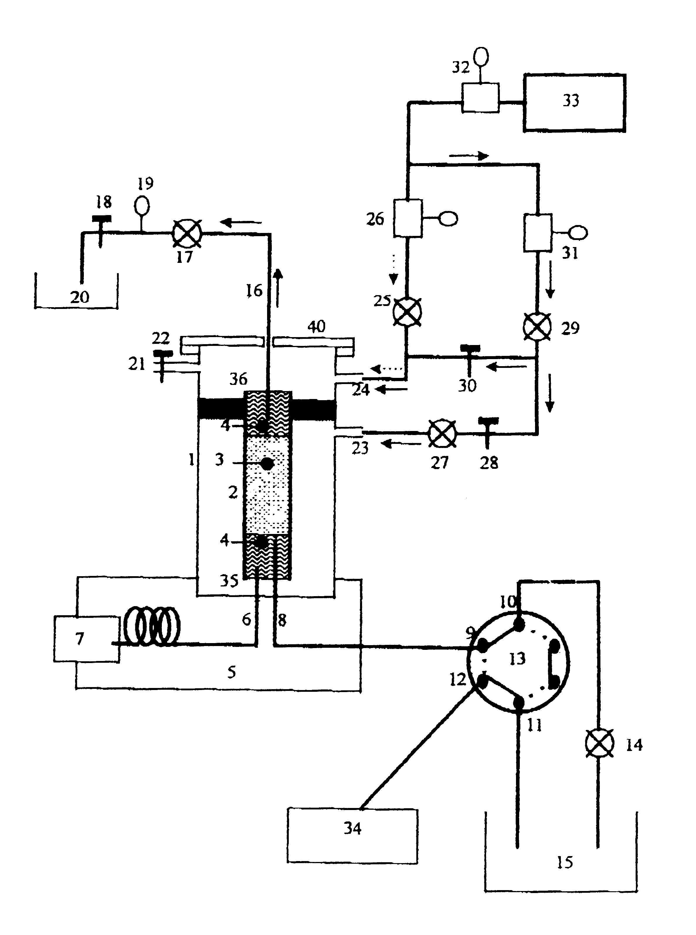
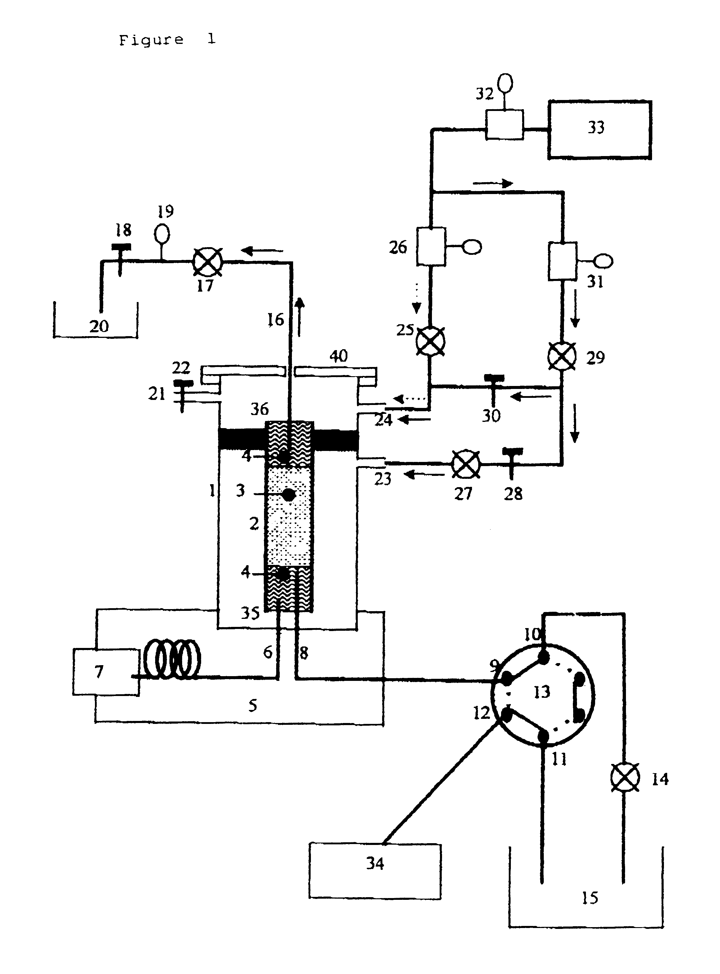
A Varian 3400 gas chromatograph was used, fitted with a PTV injector (called by the maker "PSS injector") and a thermionic detector in which a capillary column of 0.32 millimeters internal diameter and 30 meters length was fitted.

The liquid chromatograph is made up of an isocratic pump (Hewlett Packard), a U6K Injector (Waters), a column and a fixed wave length ultra-violet detector (Waters).

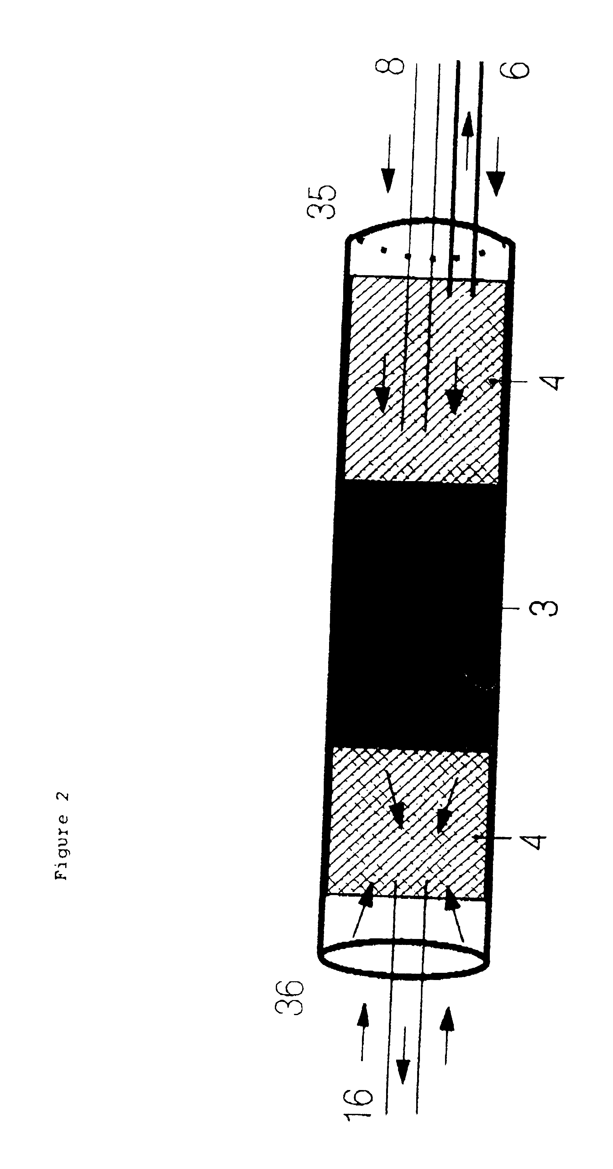
The PTV injector's glass liner 2 is 53 mm long, and has a 4.5 mm outside and 2 mm inside diameter. It is filled with 2 cm of an adsorbent 3, Tenax TA 80-100 mesh, secured by two pieces of glass wool 4 so as to prevent the adsorbent from moving.

The capillary chromatographic column 6 is placed so that it is 5 mm deep in the glass liner 2. The inside tube or capillary i.e. the first tube 8, which will carry the fraction from liquid chromatography, is a 0.32 mm inside diameter capillary which is inserted down to 15 mm depth in the glass liner. A rapid connector (Chrompack) with a gra...


PUM


Abstract

The basic structure of a PTV (programmed temperature vaporizer) injector has been considerably modified so that is can be used for the direct coupling of liquid chromatography in normal phase or reverse phase, and gas chromatography and also for the introduction of high volumes in gas chromatography. The glass tube of the injector is filled with an adsorbent. By means of a system of valves and tubes or capillary tubes, the previously selected fraction of liquid chromatography is transferred to the injector, said fraction coming in through the same extremity for introducing the gas chromatography column. The eluent is entrained by a gas stream through the adsorbent, wherein are retained the solutes, and the solvent is removed through a tube or capillary tube introduced in the injector through the opposite extremity. Thereafter, the solutes are desorbed thermally passing to the chromatography column.

Description

PRIOR ARTThe use of a direct coupling of high efficiency liquid chromatography and gas chromatography is very useful for analyzing complex mixtures. The advantages in using this multidimensional system basically centre on the possibility of combining the liquid chromatography potential as a sample preparation technique with that of gas chromatography in relation to the system's efficiency (Grob. K., On-Line Coupled LC-GC., Huthig, Heidelberg, Germany, 1991; Mondello, L.,; Dugo, G.; Bartle, K. D., J. Microcol, Sep., 1996, 8, 275-310). In this way, it is possible to avail of analysis methods which do not require the use of conventional sample preparation procedures which, apart from being laborious and unreliable, have the great disadvantage of calling for the use of relatively high volumes of polluting organic solvents.A particularly problematic aspect in connection with the use of direct coupling of liquid chromatography and gas chromatography relates to the characteristics of the i...

Claims


Application Information

Patent Timeline
11 Jun 2002
Publication
US6402947B1
IPC
G01N30/00; G01N30/12; G01N30/46; G01N30/38
CPC
G01N30/12; G01N30/461; G01N30/462; G01N2030/127; G01N2030/383; G01N30/10
Inventors
ALTAMIRANO, JESUS VILLEN; MARINA ALEGRE, MA LUISA