Ti/Tinx underlayer which enables a highly <111> oriented aluminum interconnect

a technology of aluminum interconnects and underlayers, which is applied in the direction of electrical equipment, semiconductor devices, and semiconductor/solid-state device details, etc., can solve the problems of poor electromigration resistance of polycrystalline aluminum, affecting the conductivity of contacts, and affecting the electromigration of aluminum atoms within the aluminum layer

Inactive Publication Date: 2002-07-16
APPLIED MATERIALS INC
View PDF31 Cites 34 Cited by
  • Summary
  • Abstract
  • Description
  • Claims
  • Application Information

AI Technical Summary

Problems solved by technology

However, the crystal orientation of aluminum deposited over the surface of the titanium nitride barrier layer is typically polycrystalline, and polycrystalline aluminum has poor electromigration resistance.
In the formation of integrated circuit interconnect structures, such as a Ti / TiN / TiN.sub.x stack, electromigration of aluminum atoms within the aluminum layer becomes a problem if the aluminum layer is not formed with a high degree of crystal orientation.
Electromigration of aluminum atoms can occur within filled vias as well, impairing the conductivity of the contacts.
Although such a traditionally sputtered titanium nitride-comprising layer can act as a wetting layer for hot aluminum fill of contact vias, good fill of the via generally is not achieved at substrate surface temperature of less than about 500.degree. C.
ick. Although a good fill of contact vias having 0.25.mu. diameter through holes having an aspect ratio of about 5 was achieved, the crystal orientation of the aluminum was low in content, resulting in poor electromigration (EM) performance for the aluminum interco
nnect. Further, the reflectivity of the aluminum, measured by nanoscope, with Si as a reference, was less than about 50%, so that subsequent lithography indexing was more dif

Method used


Image

  • Ti/Tinx underlayer which enables a highly &lt;111&gt; oriented aluminum interconnect
  • Ti/Tinx underlayer which enables a highly &lt;111&gt; oriented aluminum interconnect
  • Ti/Tinx underlayer which enables a highly &lt;111&gt; oriented aluminum interconnect

Examples


example two

To obtain an aluminum fill of the via where the crystallographic content was sufficiently high to prevent electromigration, the structure of the Ti / TiN / TiN.sub.x barrier layer 200 was adjusted as follows.

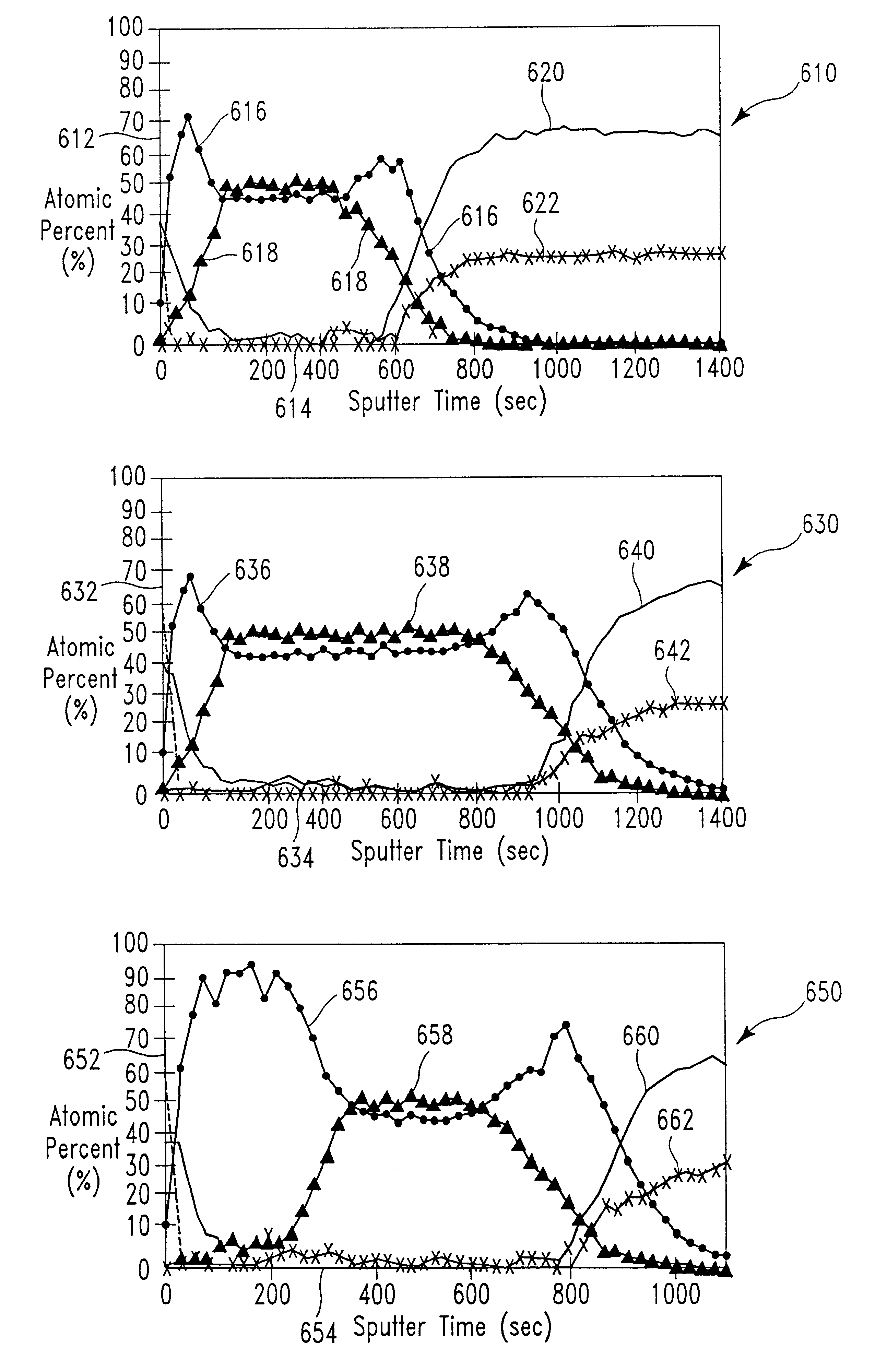
The thickness of the first layer 212 of ion-deposition sputtered Ti was about 300 .ANG.; the thickness of the second layer 214 of reactive ion-deposition sputtered TiN was about 250 .ANG.; and the thickness of the third layer 216 of reactive ion-deposition sputtered TiN.sub.x was about 250 .ANG.. The composition of the TiN.sub.x layer 216 ranged from 50 atomic % Ti initially to toward about 100 atomic % Ti toward the surface of layer 216.

Aluminum was sputtered over the surface of via 213 using traditional sputtering, at a temperature of about 400.degree. C. and at a pressure of about 2 mT.

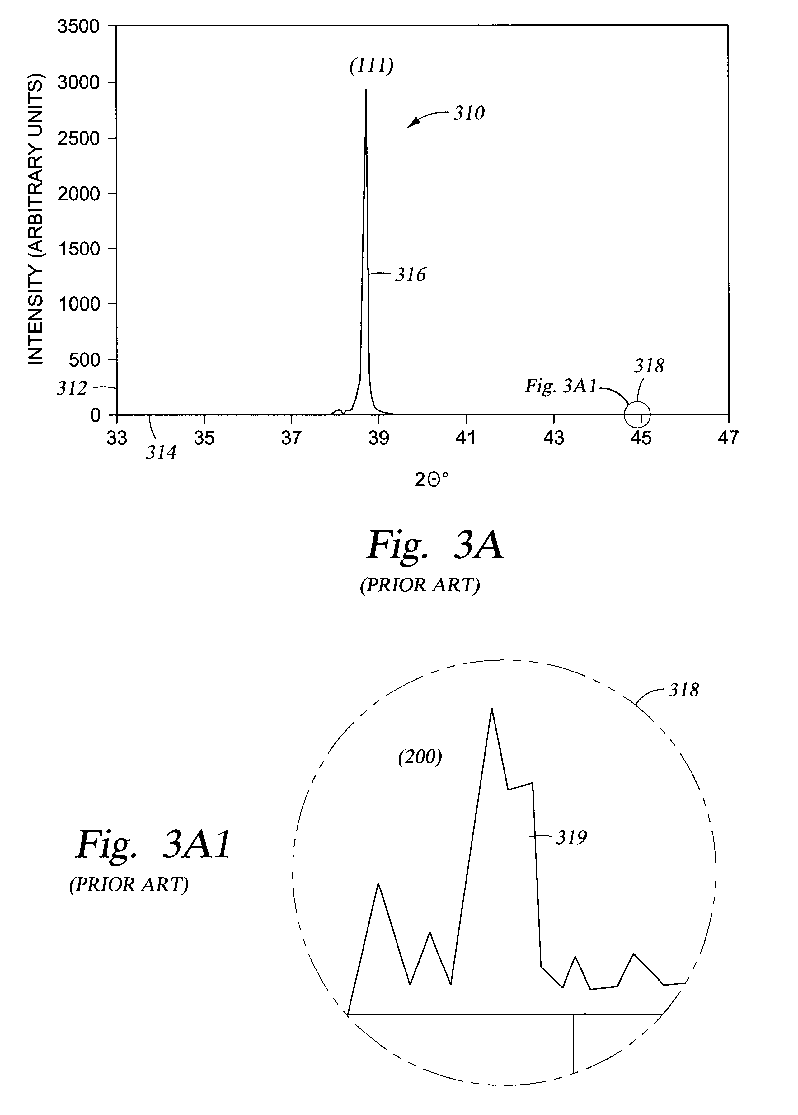
The crystallographic content of the aluminum fill was about 100% (no 200 was observed on the XRD curve). Further, the reflectivity of the aluminum surface was about 199%.

With reference to FIGS. 3...

example three

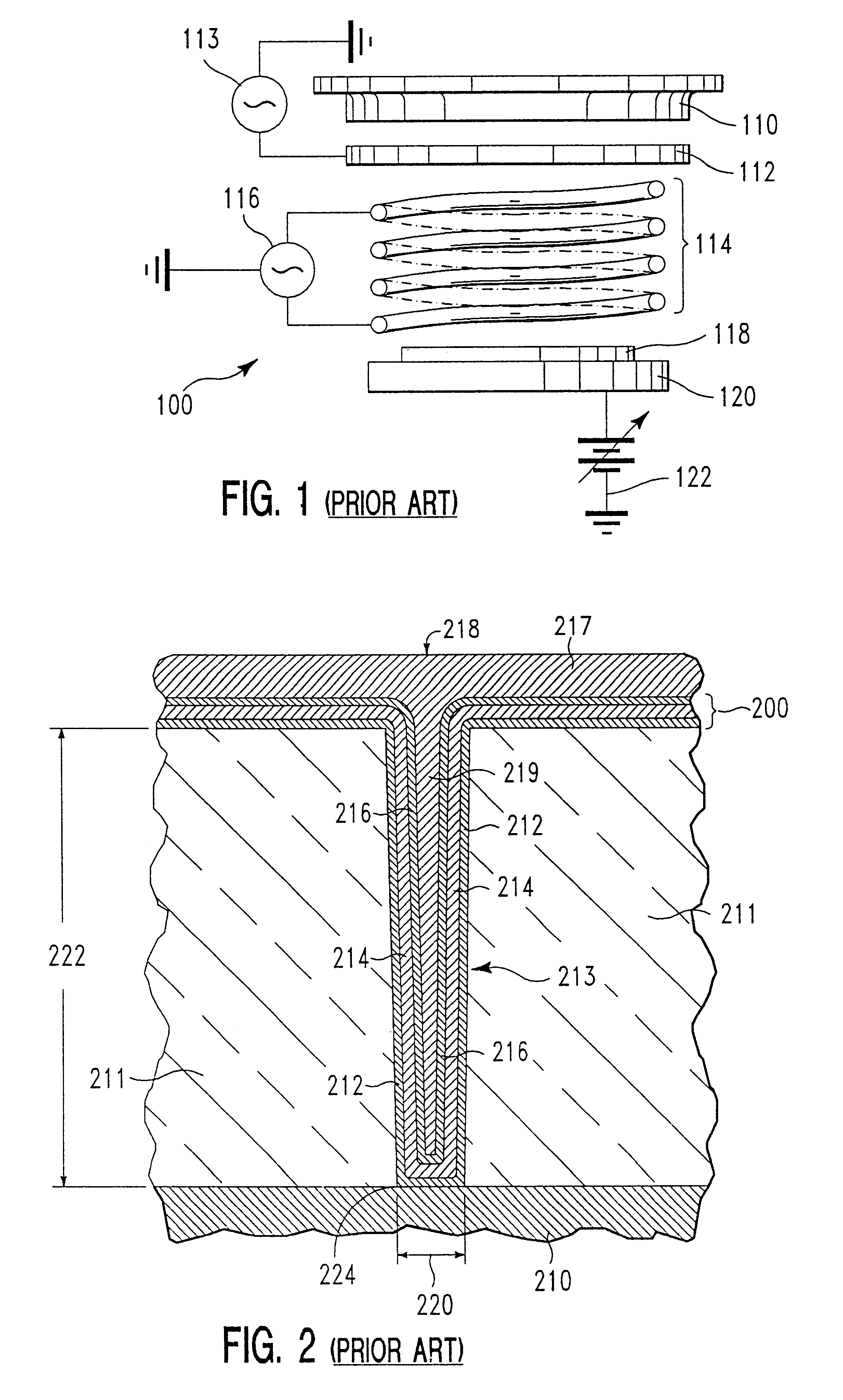
The description which follows pertains to the fabrication of a Ti / TiN / TiN.sub.x barrier layer over the surface of a 0.25.mu. feature size via having an aspect ratio of about 5:1.

With reference to FIG. 2, the via was created by dry etching through the silicon dioxide layer 211 to silicon base 210. Structure 200 comprised three layers: Ti / TiN / TiN.sub.x. The first layer of Ti was ion-deposition sputtered (IMP sputtered) upon the surface of both silicon dioxide layer 211 and silicon base 210; a second layer of reactive ion-deposition sputtered (reactive IMP sputtered) TiN layer 214 was deposited overlying first titanium layer 212; and a third ion-deposition sputtered TiN.sub.x layer 216 was deposited overlying titanium nitride layer 214. (Upon ion-sputtering of titanium layer 212, a thin layer of titanium silicide 224 is typically formed at the bottom of via 213 upon high temperature annealing). Structure 200 was then filled with a conductive layer 219.

To obtain an ion-deposition sputte...


PUM

PropertyMeasurementUnit
thicknessaaaaaaaaaa
thicknessaaaaaaaaaa
thicknessaaaaaaaaaa

Abstract

The present disclosure pertains to particular Ti/TiN/TiNx barrier/wetting layer structures which enable the warm aluminum filling of high aspect vias while providing an aluminum fill exhibiting a high degree of aluminum <111> crystal orientation. It has been discovered that an improved Ti/TiN/TiNx barrier layer deposited using IMP techniques can be obtained by increasing the thickness of the first layer of Ti to range from greater than about 100 Å to about 500 Å (the feature geometry controls the upper thickness limit); by decreasing the thickness of the TiN second layer to range from greater than about 100 Å to less than about 800 Å (preferably less than about 600 Å); and, by controlling the application of the TiNx third layer to provide a Ti content ranging from about 50 atomic percent titanium (stoichiometric) to about 100 atomic percent titanium. Preferably the TiNx third layer is formed at the end of the deposition of the TiN second layer and exhibits a Ti content gradient which begins at a stoichiometric, 50 atomic percent, Ti content and ends at a Ti content of about 100 atomic percent. The thickness of the TiNx third layer preferably ranges from about 15 Å to about 500 Å. The improved Ti/TiN/TiNx barrier layer enables the deposit of a warm aluminum interconnect or a warm aluminum via fill where the aluminum exhibits a high <111> crystallographic content. Further, the aluminum layer obtained exhibits a reflectivity of 150 percent or greater at 436 nm. A Ti/TiN/TiNx barrier layer having this structure, used to line a contact via, enables complete filling of via with sputtered warm aluminum, where the feature size of the via or aperture, is about 0.25 micron or less and the aspect ratio ranges from about 5:1 to as high as about 6:1.

Description

1. Field of the InventionThe present invention pertains to a particular (Ti or TiN.sub.x) / TiN / TiN.sub.x barrier / wetting layer structure which enables the warm aluminum filling of high aspect ratio vias while providing an aluminum fill exhibiting a high degree of <111> crystal orientation aluminum.2. Brief Description of the Background ArtTitanium nitride layers have been used in semiconductor device structures as barrier layers for preventing the interdiffusion of adjacent layers of materials such as aluminum and silicon, for example. However, the crystal orientation of aluminum deposited over the surface of the titanium nitride barrier layer is typically polycrystalline, and polycrystalline aluminum has poor electromigration resistance.In the formation of integrated circuit interconnect structures, such as a Ti / TiN / TiN.sub.x stack, electromigration of aluminum atoms within the aluminum layer becomes a problem if the aluminum layer is not formed with a high degree of <111&g...

Claims


Application Information

Patent Timeline
Patent Type & Authority Patents(United States)
IPC IPC(8): H01L23/532H01L23/52H01L21/203H01L21/3205H01L21/28
CPCH01L23/53223H01L2924/0002H01L2924/00H01L21/28
Inventor NGAN, KENNY KING-TAIRAMASWAMI, SESHADRI
Owner APPLIED MATERIALS INC
Why Eureka
Try Eureka