Solder and material designs to improve resistance to cycling fatigue in laser diode stacks

a laser diode and stack technology, applied in semiconductor laser arrangements, semiconductor laser structure details, semiconductor lasers, etc., can solve the problems of laser module affixing agent failure, laser module affixing component failure to each other, and unacceptably large number of laser module operating intermittently stop operating, etc., to achieve the effect of improving resistance to cycling fatigu

Inactive Publication Date: 2002-07-23
JDS UNIPHASE CORP
View PDF3 Cites 34 Cited by
  • Summary
  • Abstract
  • Description
  • Claims
  • Application Information

AI Technical Summary

Benefits of technology

It is an object of the present invention to improve

Problems solved by technology

Unfortunately, an unacceptably large number of laser modules that are operated intermittently stop operating after only a few thousand cycles or less.
The laser modules sometimes experience a significant increase in operating temperature before they stop operating.
Empirical studies by the inventors have determined that the cause is a failure in the affixing agent used to affix components of the la

Method used


Image

  • Solder and material designs to improve resistance to cycling fatigue in laser diode stacks
  • Solder and material designs to improve resistance to cycling fatigue in laser diode stacks
  • Solder and material designs to improve resistance to cycling fatigue in laser diode stacks

Examples


first and second embodiments

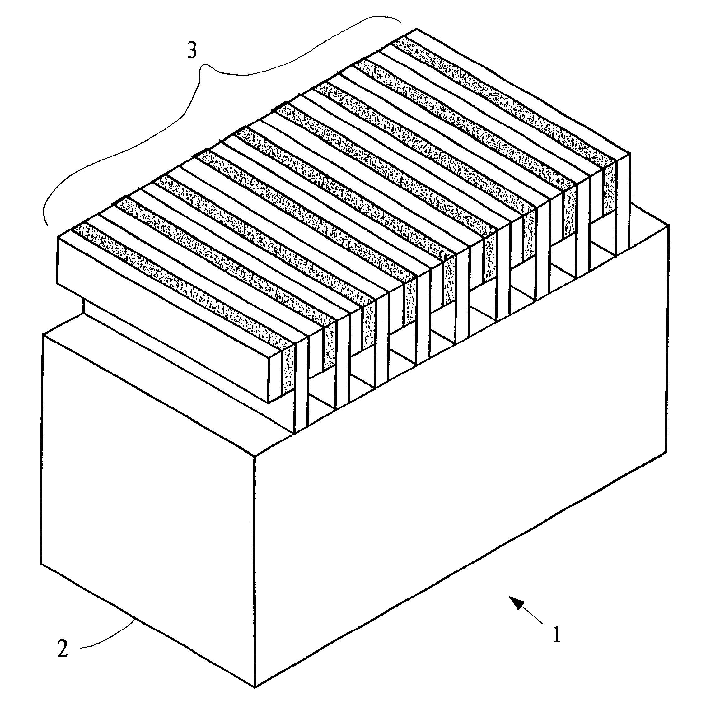
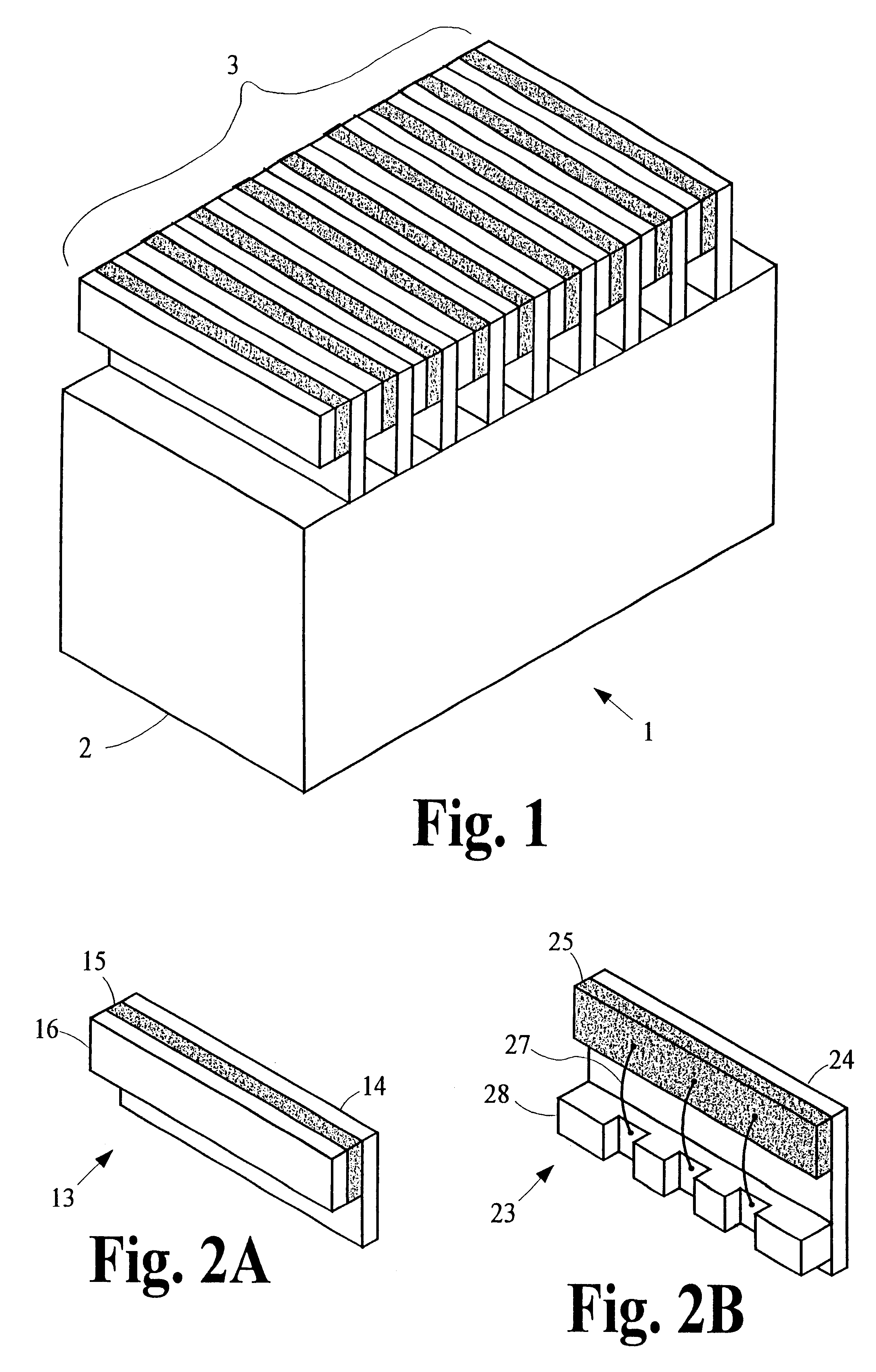
of a Laser Subassembly

FIGS. 2A and 2B are schematic perspective illustrations of two embodiments of a laser subassembly. The relative dimensions of the component parts of the embodiments in these and other figures are not necessarily shown to scale.
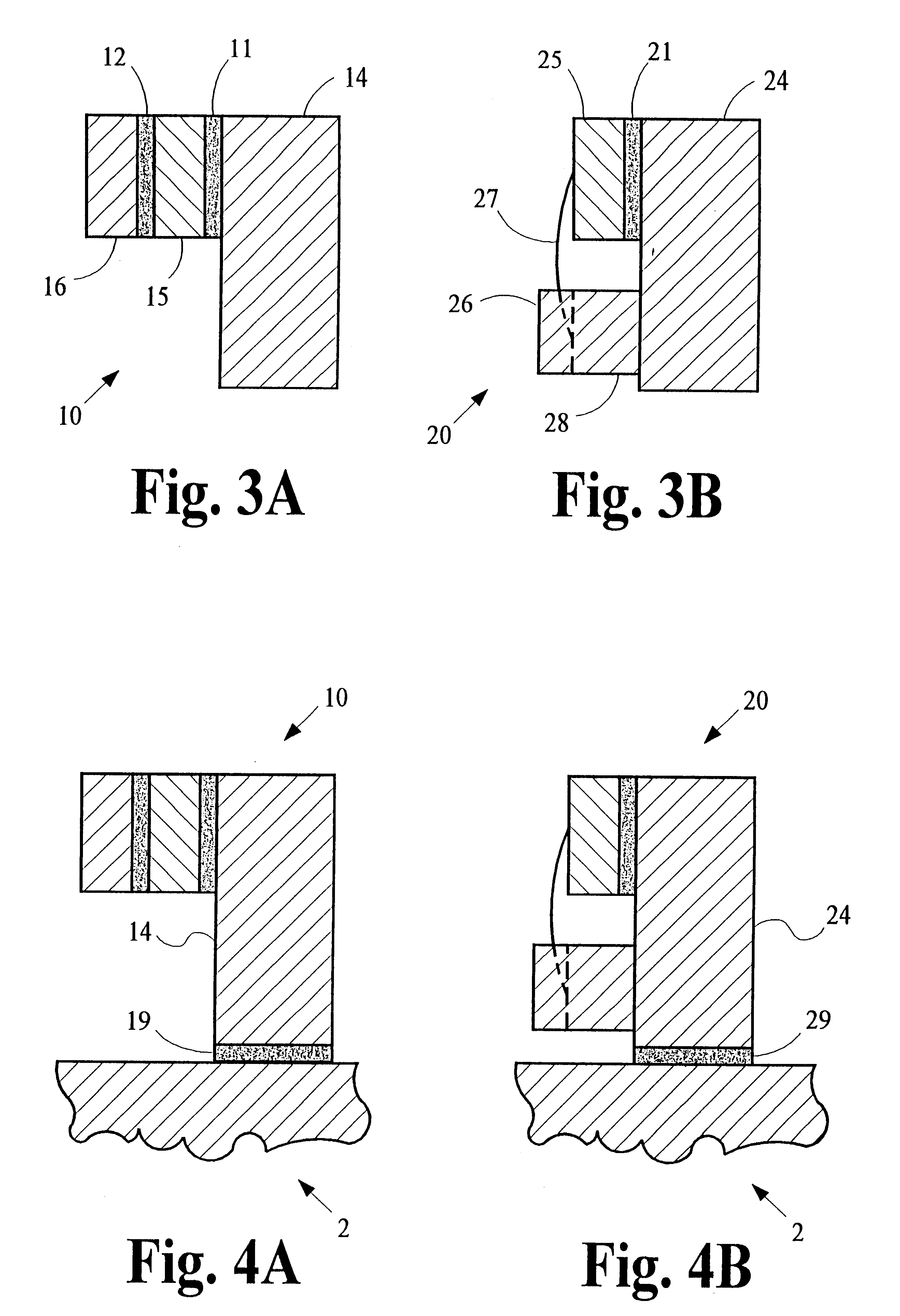
first embodiment

The first embodiment shown in FIG. 2A comprises a laser diode 15 in the shape of a bar made of a semiconductor material such as gallium arsenide (GaAs) affixed to support member 14 made of a material such as copper (Cu), copper-tungsten (CuW) or copper-molybdenum (CuMo) that is both electrically and thermally conductive. A bar 16 of electrically conductive material such as Cu or Mo is affixed to the opposite side of laser diode 15. Preferably, bar 16 is also thermally conductive. This first embodiment of laser subassembly 10 is convenient for manufacturing because it allows laser diode 15 to be tested prior to assembly into a diode stack. Support member 14 and bar 16 provide electrical contacts to the cathode and anode of laser diode 15 and they protect the brittle laser diode 15 against breakage during testing and assembly processes.

FIG. 3A is a schematic cross-section illustration of the first embodiment of laser subassembly 10. Laser diode 15 is affixed to support member 14 by af...

second embodiment

The second embodiment shown in FIG. 2B comprises a laser diode 25 in the shape of a bar made of a semiconductor material such as GaAs affixed to support member 24 made of a material such as Cu, CuW or CuMo that is both electrically and thermally conductive. A plurality of wires 27 are bonded to the surface of laser diode 25 and are bonded to depressions in a metalized surface of bar 28, which is made of an electrically insulating material such as beryllium oxide (BeO) or Aluminum Nitride (AlN) affixed to support member 24. This second embodiment of laser subassembly 20 allows laser diode 25 to be tested prior to assembly into a diode stack. Support member 24 and the metalized surface of bar 28 provide electrical contacts to laser diode 25. Support member 24 also protects the brittle laser diode 25 against breakage during testing and assembly processes.

FIG. 3B is a schematic cross-section illustration of the second embodiment of laser subassembly 20. Laser diode 25 is affixed to supp...


PUM


Abstract

Laser modules that are operated intermittently are prone to stop operating after only a few thousand cycles or less. The laser modules sometimes experience a significant increase in operating temperature before they stop operating and, in some cases, manifest an opening of the electrical circuit that connects the laser diodes in the stack of laser subassemblies. In extreme cases, the laser module disintegrates into component subassemblies. These problems arise from structural failures in affixing agents like solder that are used to affix component parts to each other. The structural failures are caused by cyclical thermal expansion and contraction of component parts that exceed the elastic limit of the solder. Resistance to global plastic deformation (creep) and to local plastic deformation (fatigue) is improved by selecting materials to reduce mechanical strain and increase resistance to creep and fatigue, by altering the structural design of the laser module to reduce mechanical strain induced into the affixing agents, and by altering operational practices to reduce the range of temperatures imposed on laser module components. One design method improves resistance to creep and fatigue by controlling the thickness of the affixing agents used to affix component parts to each other.

Description

The present invention is generally related to the construction of semiconductor-laser modules and is more particularly related to the manner in which components of a semiconductor-laser module are affixed to one another so that resistance to fatigue is improved.In some applications such as in laser printers and copiers, laser machining and in optical communication systems, lasers are operated intermittently in cycles with periods of several seconds or longer, perhaps several hours or even several days.One type of laser module that is used in communications to pump rare-earth solid-state lasers includes an array or "stack" of laser subassemblies that are each affixed by some affixing agent to a substrate of electrical insulating material. In many embodiments, the laser subassemblies are soldered to the substrate, which in turn is soldered to a heat-dissipating component that stabilizes the operating temperature of the laser module. The heat-dissipating component may be a passive heat...

Claims


Application Information

Patent Timeline
IPC IPC(8): H01S5/022H01S5/00H01S5/40H01S5/02H01S5/024
CPCH01S5/02272H01S5/02476H01S5/0021H01S5/02407H01S5/06216H01S5/4018H01S5/4043H01S5/0237
Inventor ENDRIZ, JOHN G.CHAN, JOSEWOLAK, EDMUND L.DOHLE, G. RAINER
Owner JDS UNIPHASE CORP
Why Eureka
Try Eureka