High-voltage discharge lamp with cylindrical member to mitigate thermal stress

a technology of high-voltage discharge and cylindrical members, which is applied in the direction of transit-tube circuit elements, structural circuit elements, cathode-ray/electron beam tube circuit elements, etc., can solve the problems of protruding protrusions at the leading and trailing ends, glass bulb tends to crack, protrusions scratching glass bulbs, etc., to reduce the scratching of quartz-glass bulbs and the deformation of electrodes, and reduce the risk of cracking

Inactive Publication Date: 2002-07-30
USHIO DENKI KK
View PDF4 Cites 8 Cited by
  • Summary
  • Abstract
  • Description
  • Claims
  • Application Information

AI Technical Summary

Benefits of technology

Accordingly, an object of the present invention is to provide a high-voltage discharge lamp in which it is possible to eliminate the scratching of a quartz-glass bulb and the deformation of electrodes,and to mitigate thermal stress at the time of high-temperature thermal processing and high-voltage discharge operation, as a result of which the occurrence of cracking can be prevented and sufficiently stable brightness can be obtained.
As a result of extensive research, the inventor has devised a high-voltage discharge lamp in which the joint, as well as the vicinity thereof, between at least one electrode and molybdenum foil is covered by a cylindrical member the outer and / or inner surface of which has slits, or by a mesh-like member. The inventor has found that such a high-voltage discharge lamp will no longer have its quartz-glass bulb scratched, that the electrode will no longer be deformed because it is unnecessary for the joint or the vicinity thereof to have a hermetic seal, that it is possible to mitigate thermal stress at the time of high-temperature thermal processing or high-voltage discharge operation, thereby preventing the occurrence of cracking, and that sufficiently stable brightness is obtained. The present invention has been perfected on the basis of these findings.

Problems solved by technology

When the coils are wound on the electrodes, however, protrusions are produced at the leading and trailing ends of the coils and the protrusions scratch the glass bulb.
As a consequence, the glass bulb tends to crack.
It is technically very difficult to eliminate these protrusions and to prevent the deformation of the electrodes.
Furthermore, a high-voltage discharge lamp of this kind cannot discharge stably and sufficiently stable brightness cannot be obtained.

Method used


Image

  • High-voltage discharge lamp with cylindrical member to mitigate thermal stress
  • High-voltage discharge lamp with cylindrical member to mitigate thermal stress
  • High-voltage discharge lamp with cylindrical member to mitigate thermal stress

Examples


Embodiment Construction

Preferred embodiments of the present invention will now be described with reference to the drawings.

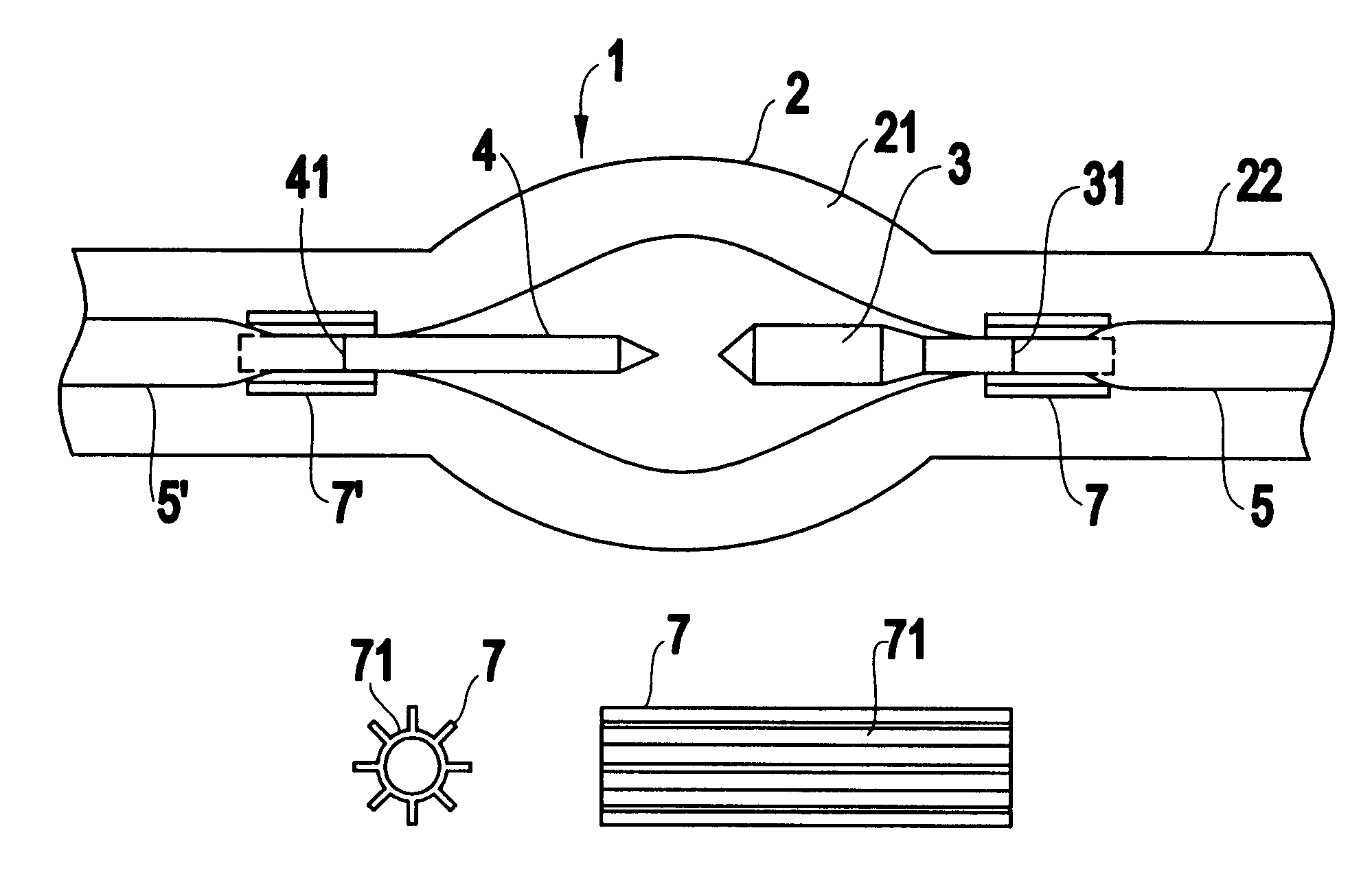
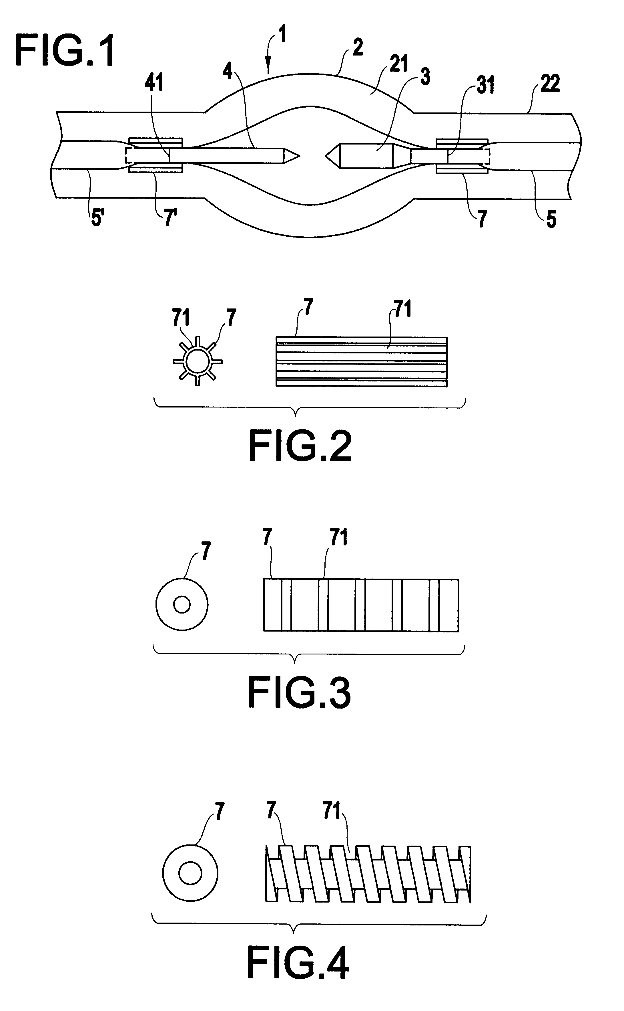
FIG. 1 is a diagram illustrating a high-voltage discharge lamp according to an embodiment of the present invention.

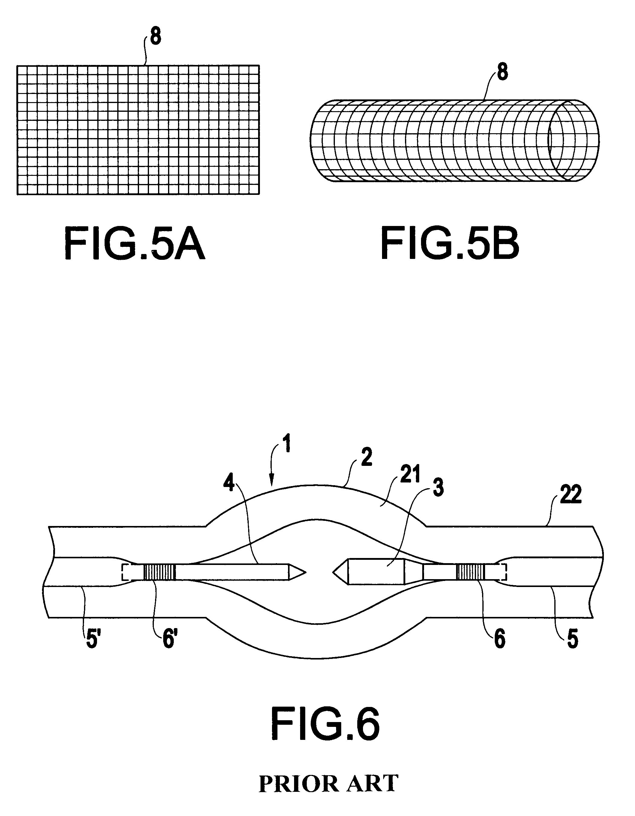
As shown in FIG. 1, a bulb 2 made of quartz glass may be one obtained naturally or synthetically. The bulb 2 may be integrally molded or may be produced by adhering two or more layers together. The shape of the enlarged or bulged portion (bulb portion) 21 that provides the light-emitting space may be spherical or ellipsoid. An anode 3 and cathode 4 preferably consist of tungsten, molybdenum or tantalum, with tungsten being particularly preferred. There is no particular limitation concerning the spacing between these electrodes. The anode 3 and cathode 4 are joined to molybdenum foils 5 and 5', respectively, by means such as welding. The molybdenum foils 5, 5' are hermetically sealed within the bulb 2 at the seal portions 22 thereof. The enlarged portion 21 having the ligh...


PUM


Abstract

A high-voltage discharge lamp has a bulb made of quartz glass, a pair of electrodes and molybdenum foils, wherein the pair of electrodes are arranged so as to oppose each other and are joined to respective ones of the molybdenum foils, and the bulb and molybdenum foils are hermetically sealed at seal portions of the bulb. The joints between the pair of electrodes and the respective molybdenum foils are covered by cylindrical members having slits on an outer surface and / or an inner surface thereof.

Description

This invention relates to a high-voltage discharge lamp and, more particularly, to a high-voltage discharge lamp in which it is possible to prevent a quartz-glass bulb from bursting at the time of high-temperature thermal processing or at the time of operation.A high-voltage discharge lamp according to the prior art has a structure of the kind shown in FIG. 6, by way of example. Specifically, a high-voltage discharge lamp 1 includes a quartz-glass bulb 2, which comprises an enlarged portion 21 that provides a light-emitting space and a seal portion 22, and a pair of opposing electrodes (an anode 3 and cathode 4) disposed within the glass bulb 2. The anode 3 and cathode 4 are joined to the molybdenum foils 5 and 5', respectively, by means such as welding. Further, the molybdenum foils 5, 5' are hermetically sealed within the bulb 2 at the seal portions 22 thereof. The enlarged portion 21 having the light-emitting space is filled with a discharge gas or the like.Coils 6, 6' comprising...

Claims


Application Information

Patent Timeline
Patent Type & Authority Patents(United States)
IPC IPC(8): H01J61/36H01J5/26
CPCH01J5/26H01J61/36H01J61/366
Inventor NISHIDA, KAZUHISAAOKI, YASUSHI
Owner USHIO DENKI KK
Why Eureka
Try Eureka