
Apparatus for self-propagating high temperature synthesis

a technology of high temperature synthesis and apparatus, which is applied in the direction of pyrolysis reactions, sub-atmospheric pressure processes, inorganic chemistry, etc., can solve the problems of low reactor capacity, inhomogeneous final product, and fundamental disadvantages of periodic operation of shs reactors

Inactive Publication Date: 2002-08-20
COMSYNTECH
View PDF12 Cites 13 Cited by
  • Summary
  • Abstract
  • Description
  • Claims
  • Application Information

AI Technical Summary

Benefits of technology

In particular, the main object of the present invention is to provide a new and improved SHS reactor in which the combustion front is prevented from expanding beyond the combustion zone and thus the combustion synthesis can be carried out safely.
The third object of the present invention is to provide a new and improved SHS reactor, in which the final product is not contaminated.
v) a retaining means capable to prevent the said layer from separating from the cylindrical periphery surface of the main drum,
Among these components can be mentioned a compacting means capable to compact the said layer before it enters the combustion zone, a scraping means for separation of the smelted layer from the forwarding means, a heating means for heating at least part of the forwarding means, before the charge resides thereonto, a heating means for heating the charge before it enters the housing, a gas supply means for supplying of at least one gas reactant as required for synthesizing the compound and with a means for evacuation and filtering of the residual gas products generated during the combustion reaction, a blowing means for cleaning the interior of the reactor chamber by blowing therethrough of a cleaning gas, a vacuum means for vacuumization the reactor chamber, at least one window for visual observation of the chamber interior, a de-contamination means for preventing contamination of the synthesized compound by the charge mixture, which did not undergo the combustion reaction.

Problems solved by technology

Unfortunately, there exist fundamental disadvantages associated with the SHS reactors operating periodically.
These reactors have relatively low capacity due to the necessity to periodically terminate the process for recharging the reactor.
Furthermore, the final product is not homogeneous due to significant temperature gradients accompanying the synthesis.
Still further disadvantage is associated with the necessity in additional equipment and energy consumption required for comminuting.
Unfortunately, despite of substantial advantage achieved due to continuous mode of operation the construction of this reactor is associated with some substantial shortcomings.
The combustion front is not prevented from expanding beyond the combustion zone up to the worm and feeder and this event can bring the reactor completely out of order or even destroy it.
The reactor is not equipped with a means for preliminary heating of the charge and thus it cannot process low exothermic mixtures.
The reactor is not provided with a means for advancing the smelted charge through the combustion zone.
The main shortcoming of the above reactor is its insufficient safety, since the reactor is not equipped with a means for monitoring the current position of the combustion front and detecting the event when the combustion front expands towards the feeder, for example due to breakdown of the drum drive or due to electricity supply breakdown.
This may be associated with insufficient reliability of operation due to possibility for discontinuation of the flow and terminating of the self-sustaining combustion.
The final product synthesized in this reactor is not pure, since the charge is not prevented from entering into receptacle for collecting the ready product and therefore it can be contaminated.
The capacity of this reactor is relatively low, since it is not equipped with a mechanism for densification of the charge and thus the charge can be easily expelled from the combustion zone and lost.
The assortment of compounds, which can be synthesized in this reactor is limited, since it is not suitable neither for processing of low exothermic charges and compounds requiring to use reactant gas, e.g. Nitrogen, Oxygen etc., nor for processing under vacuum.

Method used


Image

  • Apparatus for self-propagating high temperature synthesis
  • Apparatus for self-propagating high temperature synthesis
  • Apparatus for self-propagating high temperature synthesis

Examples


example 1

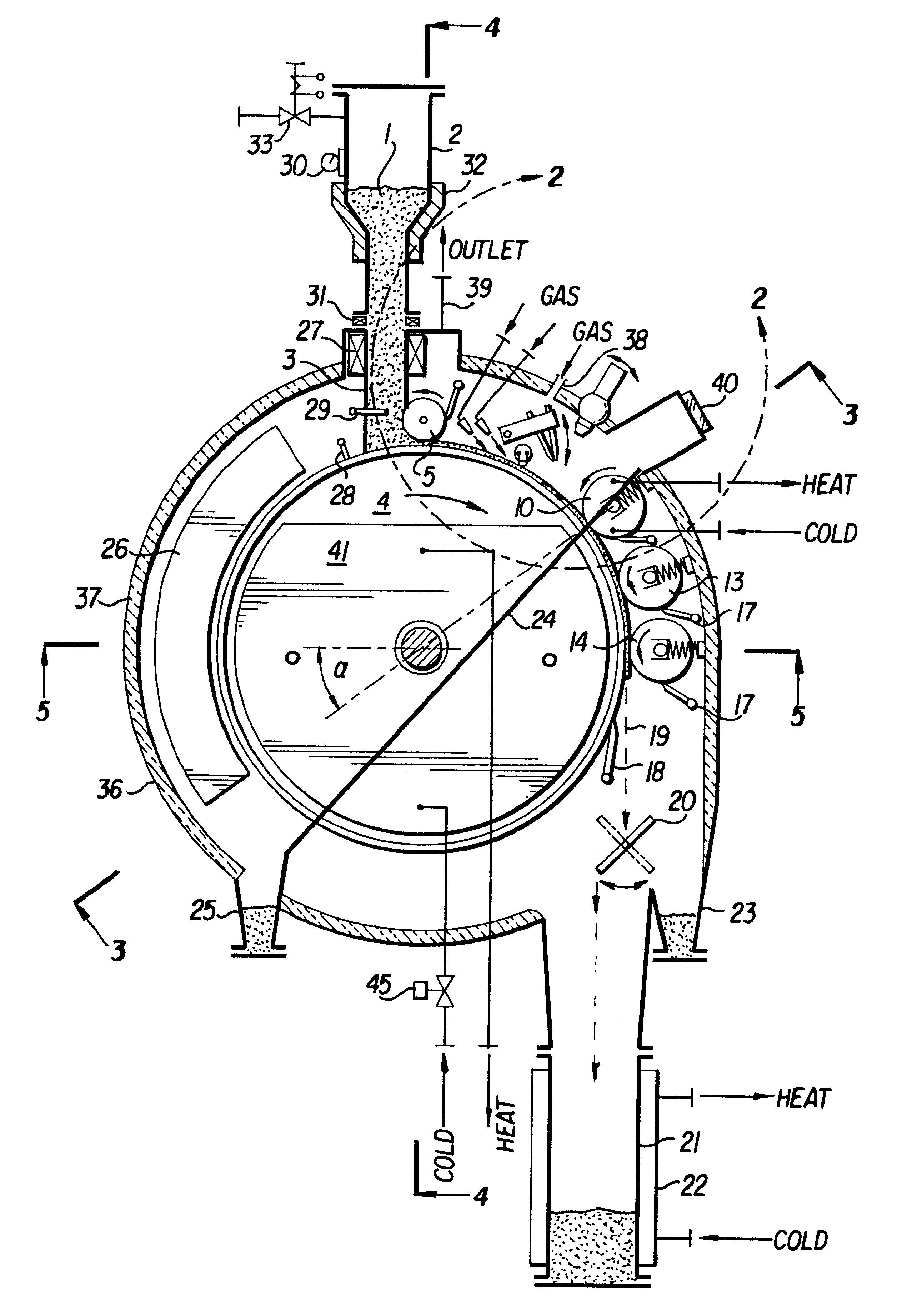
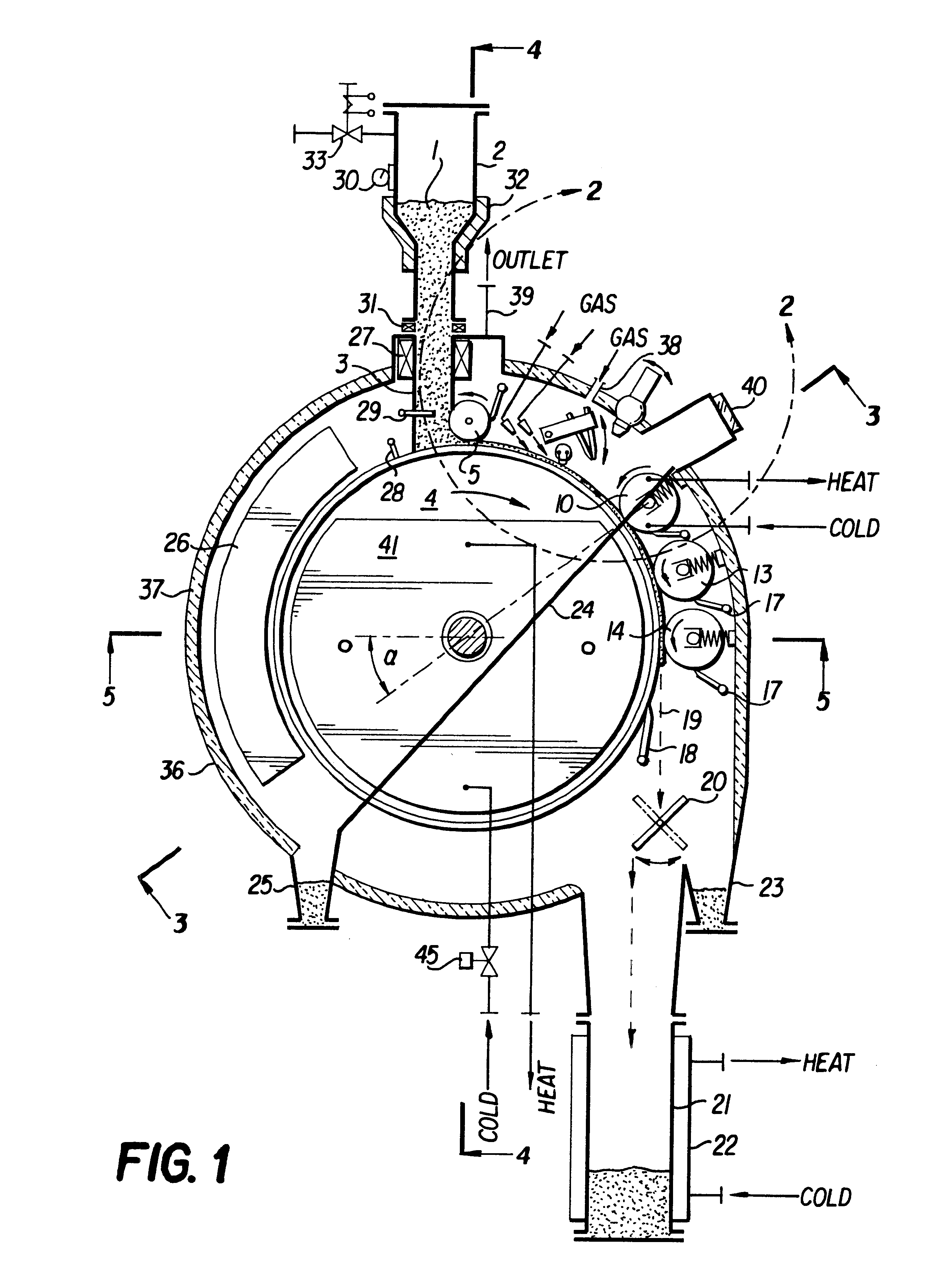
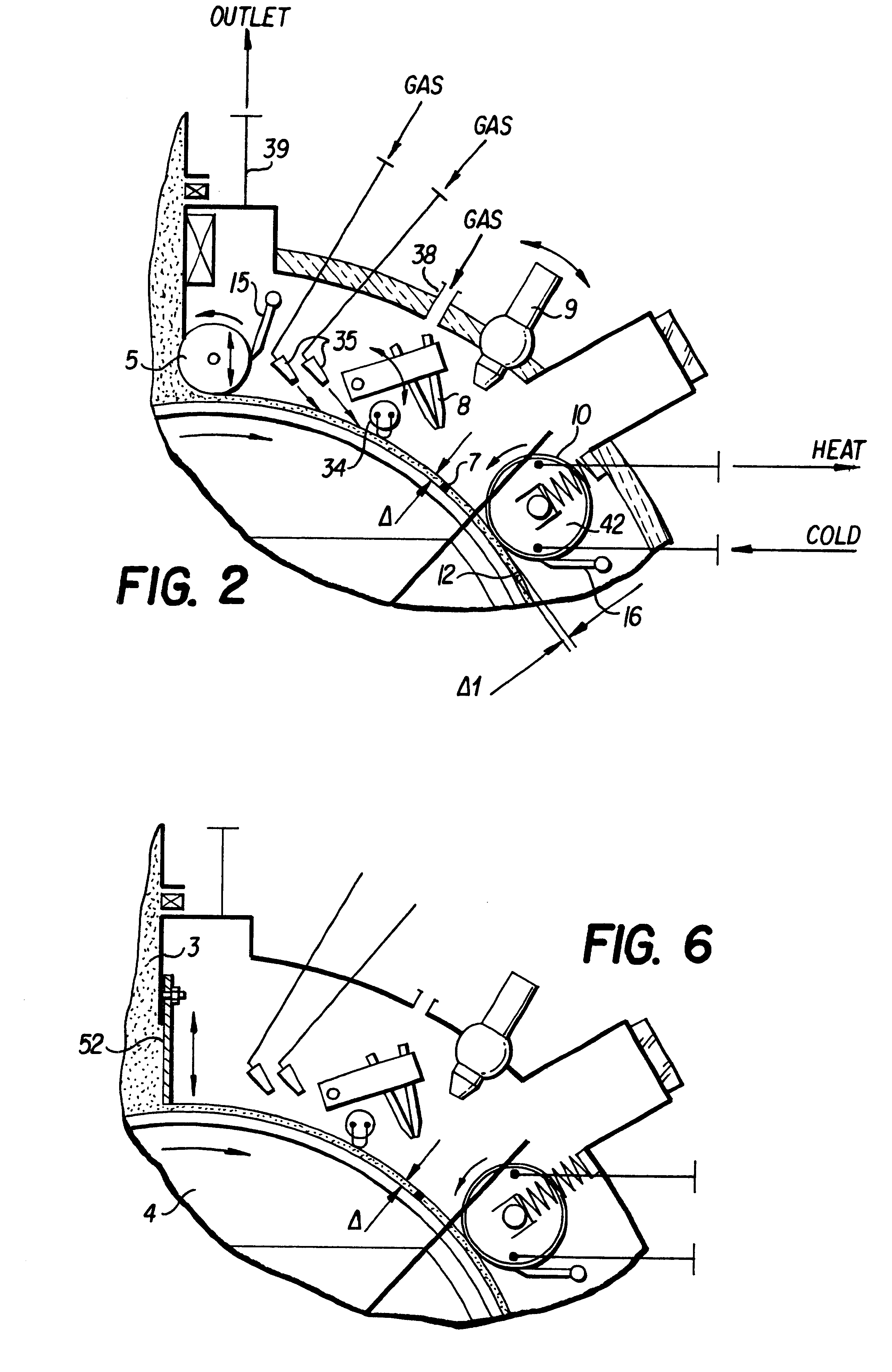
In the apparatus of the invention as shown in FIGS. 1-7 were successfully synthesized the following compounds:

Simple carbides TiC, NbC, TaC

Complex carbides TaC / NbC, TiC / WC

Silicides MoSi.sub.2, Ti.sub.5 Si.sub.3

Nitride TiN

Aluminide NiAl.

The main parameters of the reactor chamber were as follows:

Drum outside diameter--300 mm

Thickness .DELTA. of the charge mixture layer--2.5-3 mm

Thickness .DELTA. of the charge mixture layer for synthesizing of TiN--1 mm

Width of the charge mixture layer--34 mm

Capacity of the apparatus during synthesizing of TiC--7 kg / hr

Consumed power (without heating means)--0.2 kW

Mass of the apparatus--150 kg

Length of the apparatus--950 mm

Width of the apparatus--630 mm

Height of the apparatus--1850 mm.


PUM

PropertyMeasurementUnit
angleaaaaaaaaaa
temperatureaaaaaaaaaa
thicknessaaaaaaaaaa

Abstract

The present invention relates to an apparatus for self-propagating high temperature synthesis of an inorganic compound from a combustible charge mixture of initial ingredients. The apparatus comprises mechanisms for continuously feeding the combustible charge into a reaction chamber and removing the synthesized compound therefrom. The apparatus also contains sensors to control and contain the combustion inside a combustion zone of the reaction chamber.

Description

The present invention relates mainly to powder metallurgy processing, more particularly to manufacturing of powders of various inorganic compounds by so called combustion synthesis or self-propagating high temperature synthesis. This method is well known and has been successfully employed for preparation of powders from ceramic and non ceramic compounds, e.g. cermets, composites, intermetallic compounds, complex salts, etc. The present invention refers primarily to a dedicated apparatus suitable for carrying out of such self-propagating high temperature synthesis.There are known numerous publications describing self-propagating high temperature synthesis. This process is based on inducing a high temperature self-sustaining combustion reaction within a mixture of initial components, required for synthesis of a compound, providing that upon mixing these components forms an exothermic system. By virtue of very high temperatures, accompanying the combustion reaction the compound is synt...

Claims


Application Information

Patent Timeline
Patent Type & Authority Patents(United States)
IPC IPC(8): B01J19/14B01J6/00B01J12/00B01J3/00B01J12/02B01J19/00C01B31/00C01B31/30C01B21/076C01B21/00C01B13/32
CPCB01J3/006B01J6/008B01J12/02B01J19/14C01B13/324C01B21/076C01B31/30B01J2219/00191C01B32/90
Inventor KOPYT, YURI
Owner COMSYNTECH
Learn More