
Tapered fiber gratings and applications

a technology of tapered fiber and gratings, applied in the direction of optical waveguide light guides, instruments, optics, etc., can solve the problems of complex transmission of multiplexed signals without interfering wavelength signals or interference between them, unwanted off-wavelength signals affecting network reliability, and adverse effect on insertion loss and signal attenuation

Inactive Publication Date: 2002-09-03
ARROYO OPTICS
View PDF9 Cites 29 Cited by
  • Summary
  • Abstract
  • Description
  • Claims
  • Application Information

AI Technical Summary

Problems solved by technology

Transmission of multiplexed signals without intervening wavelength signals or interference between them is complicated by the need for low loss both above and below the selected center wavelengths.
In-fiber (e.g., erbium) amplifiers have a relatively wide window (e.g., 35 nm) and unwanted off-wavelength signals affect network reliability.
Optical wave energy interacts with active and passive components which can have an adverse effect on insertion loss and signal attenuation, as well as introducing undesired backreflection.
This places a limitation on the placement of the signals and channels which can pass through a fiber grating.
Tapered devices reduce the dopant core to a vestigial size and function, and so do not usefully employ Bragg gratings.
The presence of a taper dramatically reduces diffraction efficiency, typically to less than 1%, and the problems arising from the limited splitting of lossy modes from backreflected wavelengths still remain.
The splitting problem also exists in most fused couplers which are grating assisted, because light is largely confined in the original cores and overlaps only at the evanescent tails of the optical modes

Method used


Image

  • Tapered fiber gratings and applications
  • Tapered fiber gratings and applications
  • Tapered fiber gratings and applications

Examples


example 1

Add / Drop Filter

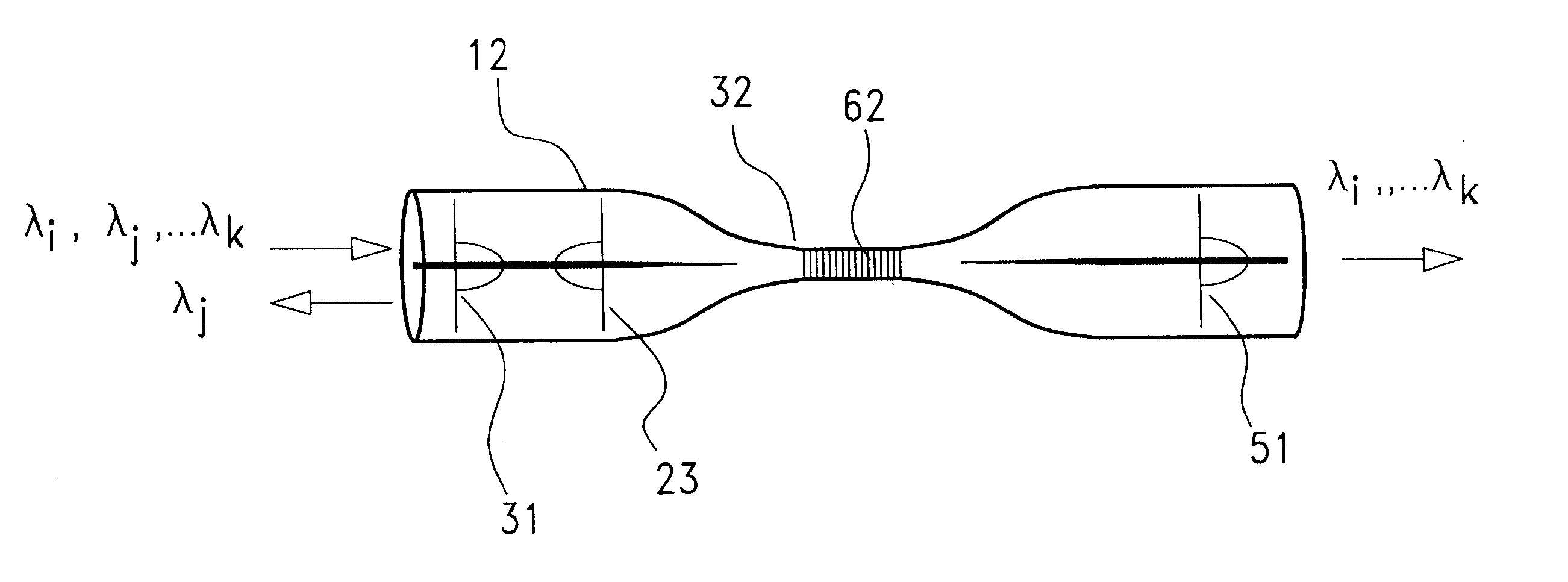
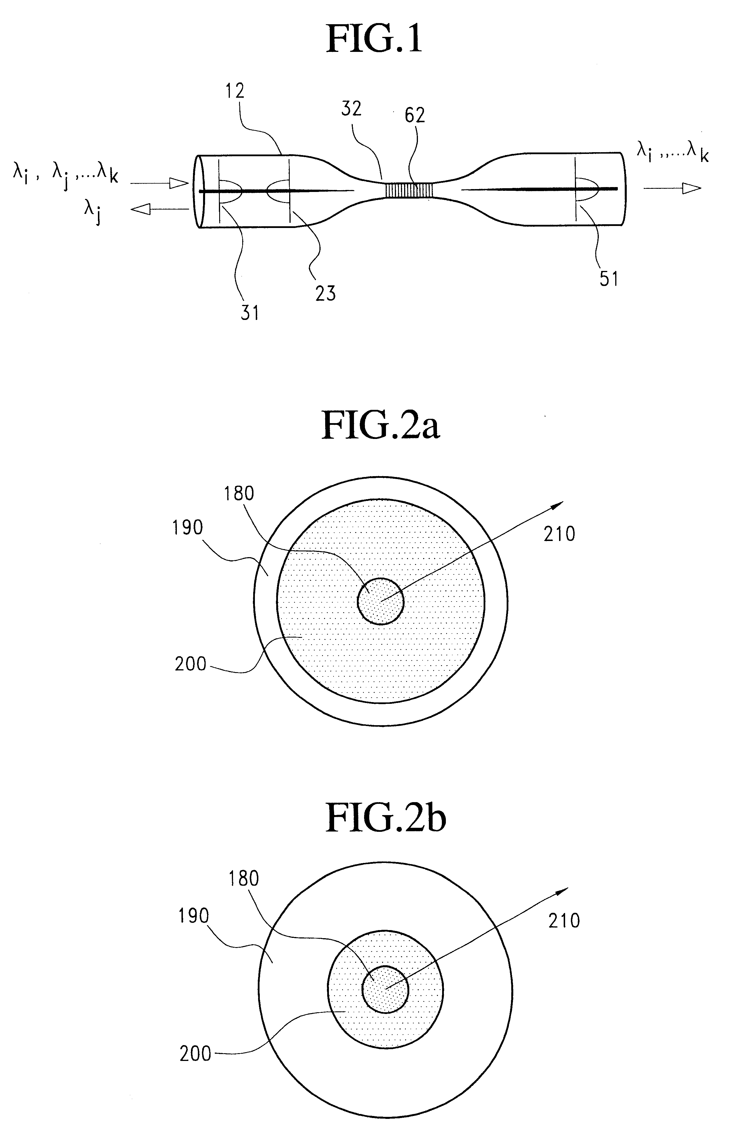
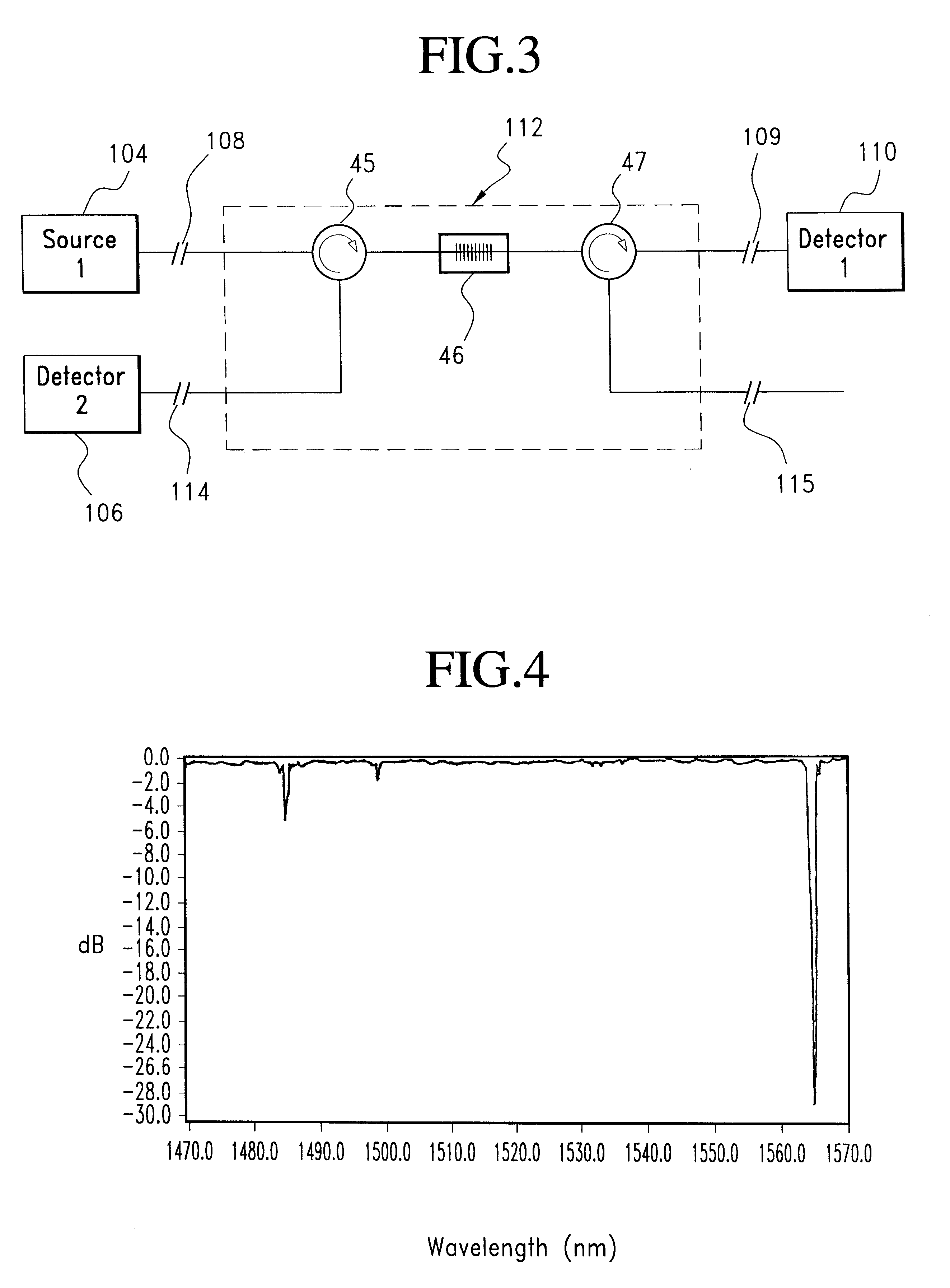
A low insertion loss device to selectively add or drop an optical channel of a particular wavelength with high efficiency is a building block for WDM networks. A functional representation of this device based on a tapered fiber grating 46 and circulators 45, 47 is illustrated in FIG. 3. The input optical fiber 106 carries N channels of information, each channel at a different center wavelength .lambda..sub.j. The tapered fiber grating 45 backreflects a particular channel .lambda..sub.i. This backreflected channel is routed onto the first output optical fiber 114 by a fiberoptic circulator 45, while all other channels travel uninterrupted through the aforementioned taper region to the second output optical fiber 109.

This device can also operate as an add filter by adding a second circulator 47 along the second output optical fiber 109, and using fiber 115 as the add input. A particular channel .lambda..sub.j is added to a fiber containing channels at other wavelengths ...

example 2

Tapered Doped-Cladding Fiber Grating Fabrication

One optical fiber whose index profile is illustrated in FIG. 2a, where the doped portion of the cladding 200 extends out to a diameter of 82 um and the core 180 is 9 um, is tapered such that the diameter is reduced from 125 um to 3.2 um over a length of approximately 25 mm The tapering is accomplished by pulling on opposite ends of the optical fiber while heating the optical fiber with an oxygen-hydrogen torch. The taper waist is subsequently exposed to a UV interference pattern generated by illuminating a silica phase mask of period 1.1 um with a focused beam of 244 nm cw illumination. This produces an optical interference pattern with a period of approximately 0.5 um. The grating is recorded for 5-20 minutes within a high pressure deuterium gas environment. The elongated region of the taper is subsequently epoxied to a temperature compensated prepackage to provide mechanical strength. The wavelength trace of light backreflected is il...

example 3

Four Channel Add-Drop Multiplexers

A static 4 channel add / drop multiplexer 301 can be fabricated by inserting two three port circulators 302, 303 along a throughput line 304, with four tapered fiber gratings 305, 306, 307, 308 placed in series between the circulators (FIG. 6). These four tapered fiber gratings direct the four selected wavelength channels into the circulators, which direct the backreflected channels into the add / drop loop 309. Once in the add / drop loop, the individual channels are added and dropped by four grating assisted mode couplers 310, 311, 312, 313. The backreflection wavelengths .lambda..sub.i, .lambda..sub.j, .lambda..sub.k, .lambda..sub.l of each tapered fiber grating 305, 306, 307, 308 is precisely matched to the drop wavelength of a corresponding grating assisted mode coupler 310, 311, 312, 313. Because of the limited spectral bandwidth traveling within the add / drop loop 309, the individual add / drop filters do not need to exhibit a drop-backreflection spli...


PUM


Abstract

Optical filter devices in accordance with the invention are based on tapered optical fibers having transversely distributed refractive index variations in a small diameter waist region where waves are propagated in combined cladding / air-guided modes. The grating has a periodicity selected for reflection of a selected center wavelength and the waist diameter and grating pattern split the wavelengths of the lossy cladding modes from the backreflected signals by more than 10 nm. Such wavelength selective optical fiber devices have a variety of applications. In one application, a tapered fiber grating with optical circulators is used to add or drop optical signals for communication via a common transmission path. In another application, the tapered fiber grating is used with grating assisted mode couplers and circulators to form an add / drop multiplexer. In another application, these components are used with optical switches to produce programmable add / drop filters and crossconnects.

Description

The present invention relates to the communication of signals via optical fibers, particularly to tapered optical fibers and couplers. More particularly, the invention relates to wavelength selective tapered fiber gratings, add / drop filters and optical circuits for wavelength division multiplexed systems.DESCRIPTION OF RELATED ARTLow loss, wavelength selective filters are important components for optical fiber communication networks based on wavelength division multiplexing (WDM). WDM enables an individual optical fiber to transmit several or many channels simultaneously, at different spaced apart center wavelengths. As the art has developed, standardized wavelength band parameters have been set, for the number of channels, the total wavelength band, and the separation between channels. As a basic example, 30 nm may be devoted to a band of 4 channels having 10 nm separations between the center wavelengths.Transmission of multiplexed signals without intervening wavelength signals or ...

Claims


Application Information

Patent Timeline
IPC IPC(8): G02B6/34
CPCG02B6/021G02B6/02119G02B6/29317G02B6/29334G02B6/2932G02B6/29328G02B6/29383
Inventor RAKULJIC, GEORGE A.KEWITSCH, ANTHONY S.
Owner ARROYO OPTICS
Learn More