Laser surgical handpiece with photon trap

a laser and handpiece technology, applied in the field of laser surgical instruments, can solve the problems of blurred vision, decreased vision, and inability to properly pass light to the retina, and achieve the effect of minimizing potential damage to the ey

Inactive Publication Date: 2002-09-24
PARADIGM MEDICAL INDS
View PDF16 Cites 63 Cited by
  • Summary
  • Abstract
  • Description
  • Claims
  • Application Information

AI Technical Summary

Benefits of technology

The present invention relates to the field of laser surgical instruments for use in optical surgery. More particularly, the present invention relates to a device that uses laser light to ablate ocular tissue, while

Problems solved by technology

If the lens becomes cloudy, light cannot pass to the retina properly and vision is blurred and decreased.
But as the lens continues to change, several specific symptoms may develop including blurred vision, sensitivity to light and glare, increased nearsightedness, or distorted images.
However, cataracts can affect all ages because they can result from injury, heredity, chronic eye disease, or system-wide diseases such as diabetes.
But if it continues to develop, vision is impaired, and treatment is necessary.
However, vision was still blurred because the patient lacked a lens to focus light.
Although phacoemulsification is an improvement over earlier methods because it can be performed through a small incision, the surgical procedure is difficult and requires highly specialized surgical skills.
In addition to the need to carefully control fluid flow through the surgical site, the heat and the vibration of the ultrasonic needle can damage adjacent ocular tissue.
Thus, this technique has been found to be less than ideal and improvements in technique and equipment have been sought.
Even though the use of lasers in ocular surgery represents a large advance, there are still problems which arise.
While heat and vibration are reduced over that experienced in ultrasonic phacoemulifiers, laser devices have the potential of damaging surroundi

Method used


Image

  • Laser surgical handpiece with photon trap
  • Laser surgical handpiece with photon trap
  • Laser surgical handpiece with photon trap

Examples


Embodiment Construction

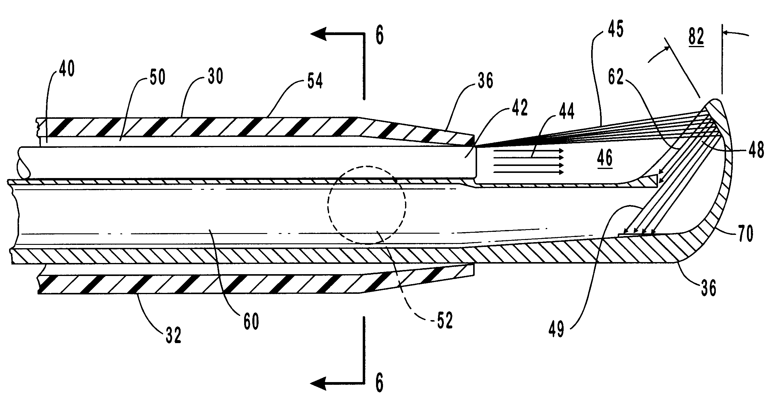
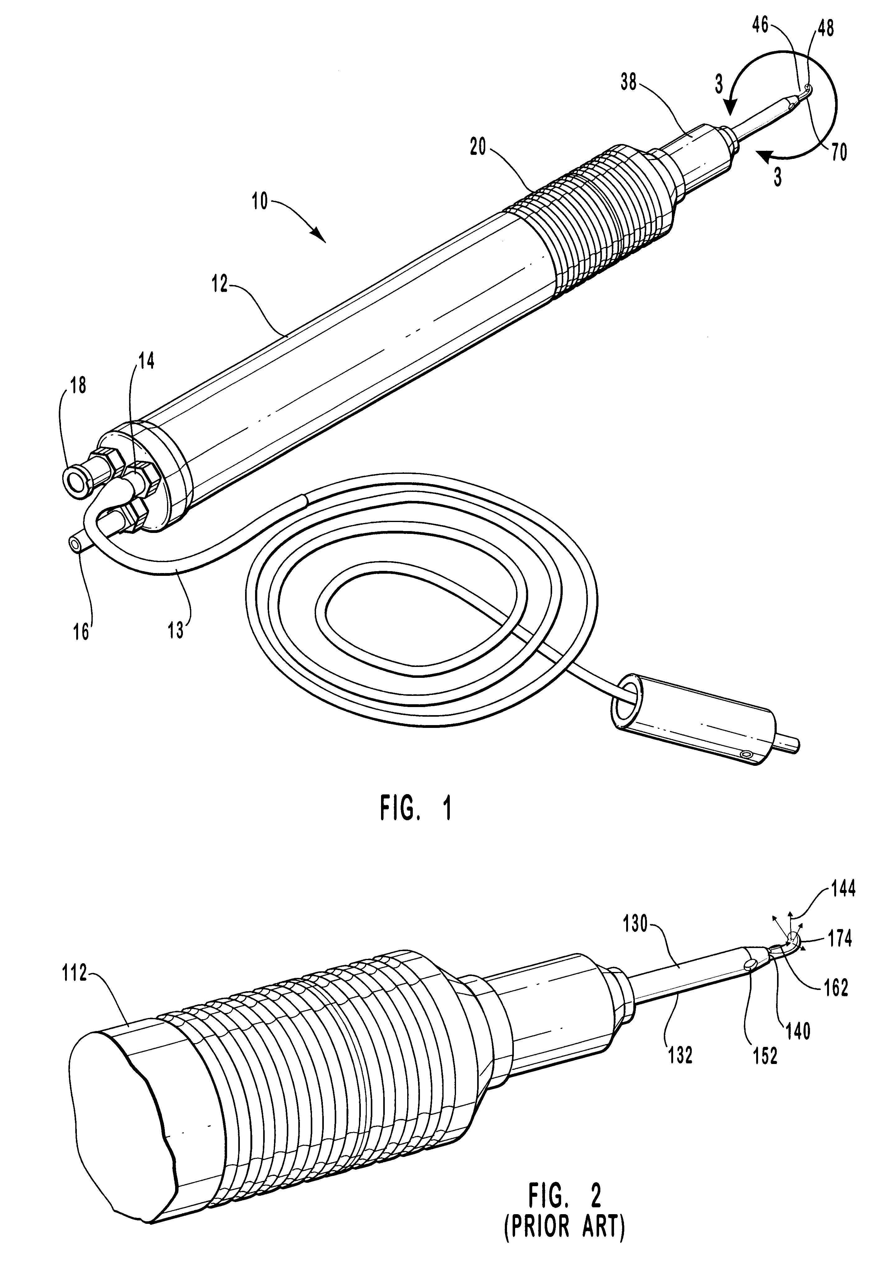
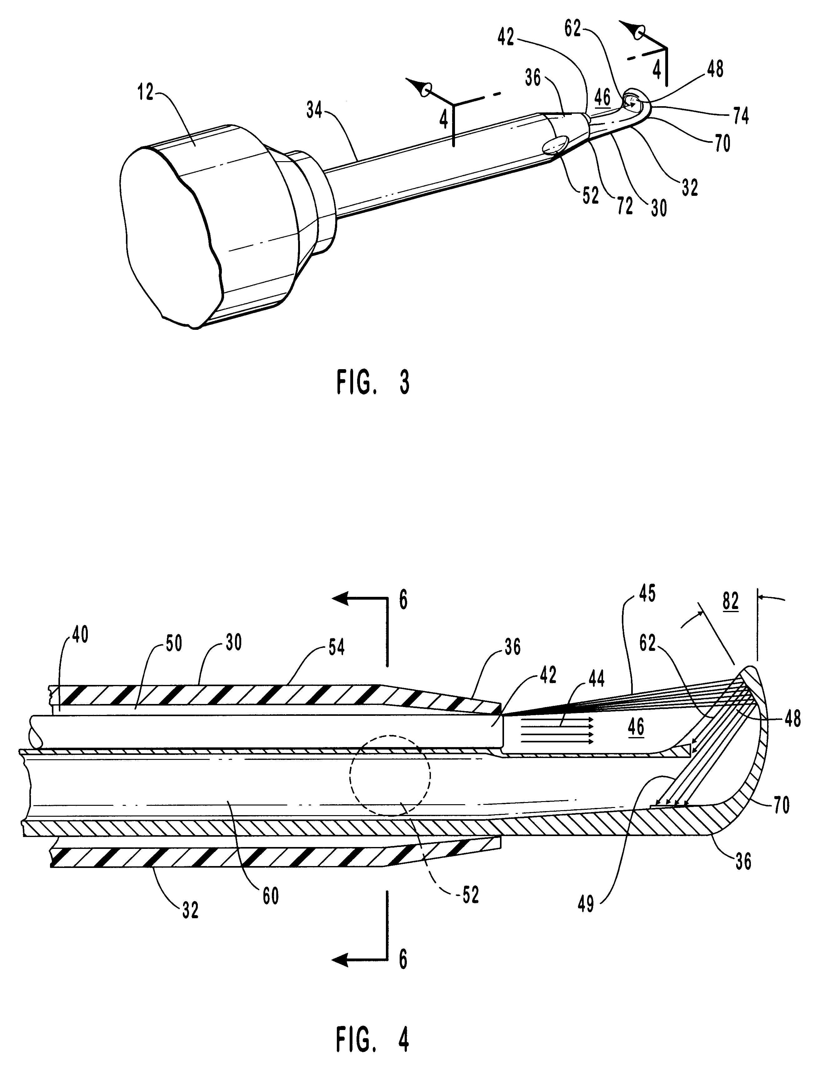
It will be readily understood that the components of the present invention, as generally described and illustrated in the drawings herein, could be arranged and designed in a wide variety of different configurations. Thus, the following more detailed description of the embodiments of the system and method of the present invention, as represented in FIGS. 1 and 3 through 6, is not intended to limit the scope of the invention. The illustrations are merely representative of certain, presently preferred embodiments of the invention. Those presently preferred embodiments of the invention will be best understood by reference to the drawings, wherein like parts are designated by like numerals throughout.

Those of ordinary skill in the art will, of course, appreciate that various modifications to the details of the drawings may easily be made without departing from the essential characteristics of the invention. Thus, the following description of the Figures is intended only as an example, a...


PUM


Abstract

A laser surgical device for removal of intraocular tissue including a handpiece and a tip. The handpiece has a sleeve that creates a passage way for irrigation fluid. An optic fiber or similar light conveying means is contained within the handpiece. A passageway for aspiration is included in the handpiece and continues into the tip. The tip is configured with a photon trap that captures stray laser light and prevents it from continuing into the eye.

Description

1. FIELD OF THE INVENTIONThe present invention relates to the field of laser surgical instruments for use in optical surgery. More particularly, the present invention relates to a device that uses laser light to ablate ocular tissue, while at the same time minimizing potential damage to the eye during surgery by providing a structure which is capable of trapping laser light used in the surgical procedure.2. TECHNICAL BACKGROUNDThe eye has an anterior chamber and a posterior chamber which are separated by a normally transparent lens. The lens is a clear tissue located behind the pupil. The lens works with the transparent cornea, which covers the eye's surface, to focus light on the retina at the back of the eye. The lens of the eye is clear at birth, but is one of the first parts of the body to show the effects of aging. If the lens becomes cloudy, light cannot pass to the retina properly and vision is blurred and decreased. This clouding of the lens is known as a cataract.As the len...

Claims


Application Information

Patent Timeline
IPC IPC(8): A61F9/007A61F9/008A61B19/00A61M1/00
CPCA61F9/00802A61B2019/4045A61F9/00736A61F2009/0087A61F2009/00887A61B2090/0445
Inventor MOTTER, THOMAS F.SMITH, TODD H.MILLAR, ROBERT M.
Owner PARADIGM MEDICAL INDS
Why Eureka
Try Eureka