Method for making thin, flat, dense membranes on porous substrates

a porous substrate and colloidal deposition technology, applied in the direction of non-aqueous electrolyte cells, cell components, electrochemical generators, etc., can solve the problems of high cost of capital equipment and/or operating costs for several of these approaches, a considerable barrier to their commercialization, and inhomogeneity of film and substrate, so as to achieve high quality

Inactive Publication Date: 2002-10-01
RGT UNIV OF CALIFORNIA
View PDF6 Cites 74 Cited by
  • Summary
  • Abstract
  • Description
  • Claims
  • Application Information

AI Technical Summary

Benefits of technology

It is a general object of the present invention to provide a method of thin, dense colloidal deposition and sintering whereby high quality films of a wide variety of ionic and mixed ionic-electronic conductors can be deposited onto highly porous electrode substrates.

Problems solved by technology

Many of these approaches have allowed the fabrication of good quality films, however, the high cost of capital equipment and / or operating costs for several of these approaches presents a considerable barrier to their commercialization.
However, the procedure also led to inhomogeneities in the film (differential densification) as well as different shrinkage rates for film and substrate.
This often led to significant edge curl, which poses significant or insurmountable problems in terms of ultimate use of these structures in solid oxide fuel cell (SOFC) stacks.
Furthermore, application of the film by dip coating or application of wet dispersion often led to mud cracking and / or variations in film thickness and local green density of the film across the substrate surface.
Poor understanding of these parameters often leads to electrolyte films of low density (pinholes) or cracked films composed of islands of high density film.
Even in cases where the shrinkage of film and substrate are sufficiently close to generate dense electrolyte films, residual stresses can lead to highly distorted films with significant curling.

Method used


Image

  • Method for making thin, flat, dense membranes on porous substrates
  • Method for making thin, flat, dense membranes on porous substrates
  • Method for making thin, flat, dense membranes on porous substrates

Examples


example 1

Ionic (Oxygen) Conductor on Cermet Precursor--YSZ Thin Film on Porous NiO / YSZ Substrate

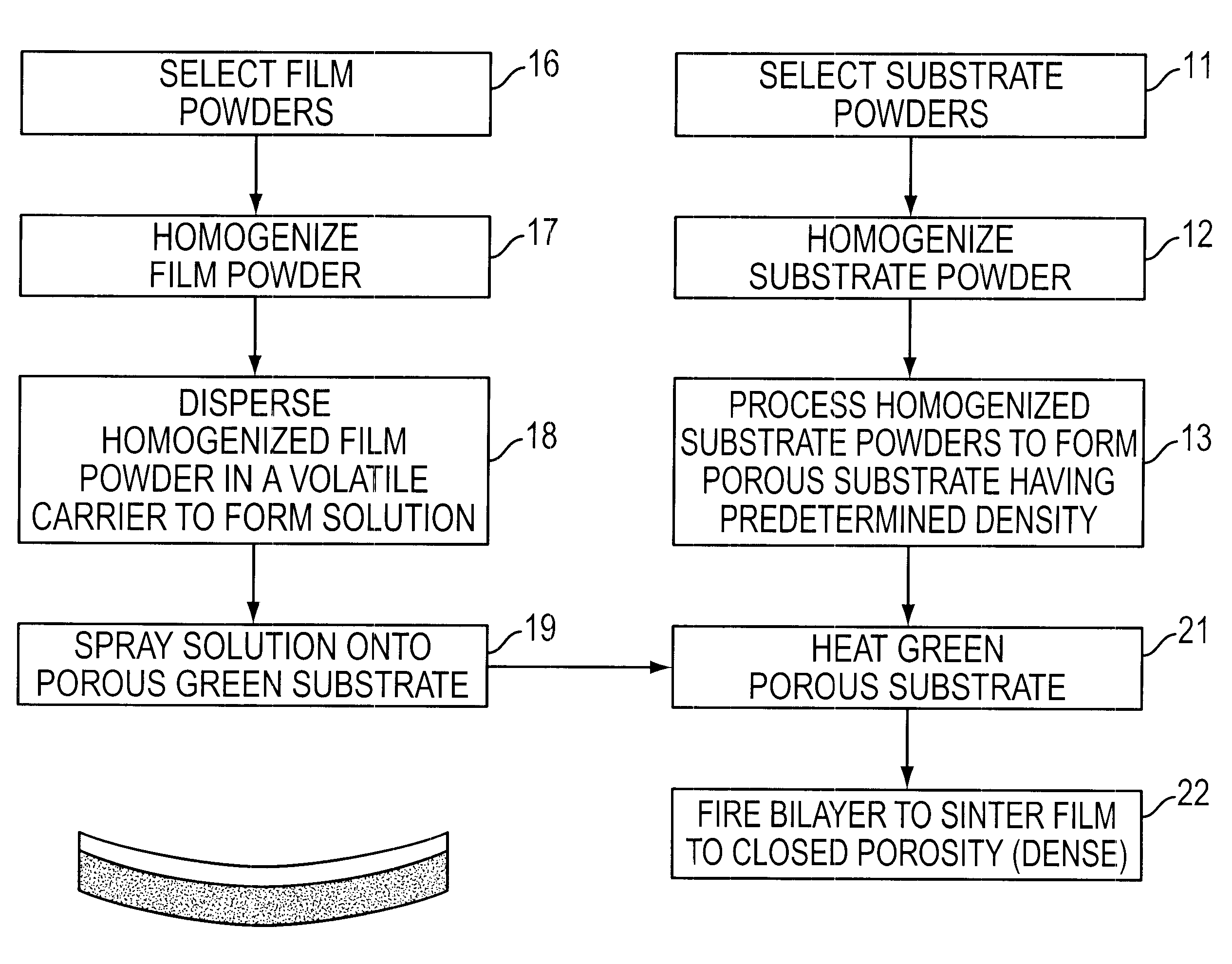
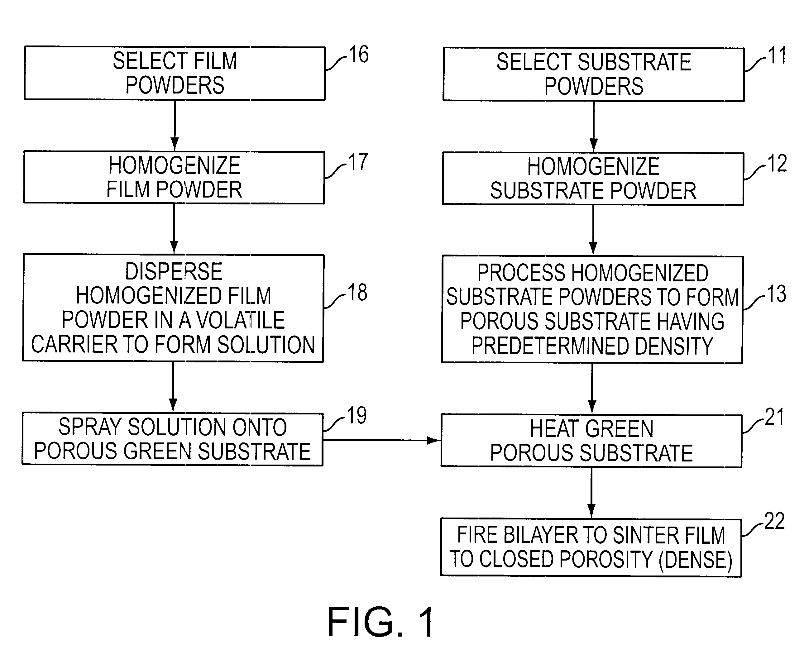
Yttria stabilized zirconia (YSZ), NiO and a binder / pore former (corn starch) were obtained from commercial vendors (Tosoh Corporation, J.T. Baker Inc., and CPC International Inc. respectively). The substrate powders consisting of 54 wt % NiO, 36 wt % YSZ and 10 wt % corn starch were attritor milled with zirconia milling balls at 550 rpm for 3 hours in acetone. The powder was dried and sieved to <100 .mu.m using a stainless steel wire sieve. 2.5 g of powder were uniaxially pressed in a 3.81 cm (1.5 in) steel die at 10,000 lbs. The substrate was fired in an air furnace using the following schedule: 1.degree. C. / min to 400.degree. C., hold for 1 hour, 5.degree. C. / min to 900.degree. C., hold for 8 hours, 5.degree. C. / min to room temperature. The green substrate now had sufficient strength for thin film deposition. The substrate was placed on a hot plate and held at .about.100-150.degree. C. while .ab...

example 2

Concave / convex YSZ on NiO / YSZ Substrates

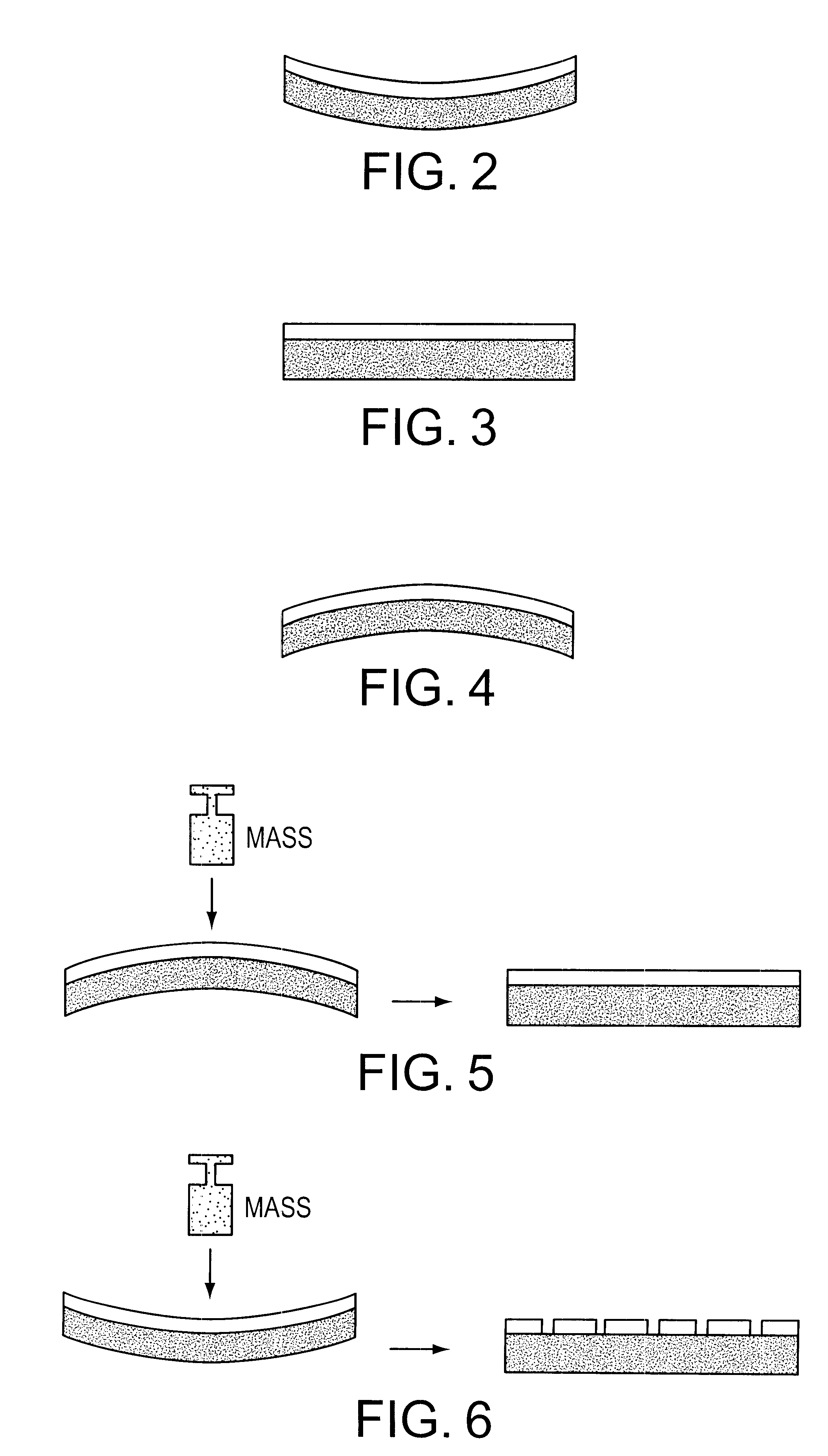
A bilayer was prepared in an identical manner as Example 1 with the exception that no alumina weight was placed on the structure during sintering. The bilayer sintered without the alumina weight results in a convex disk (thin film side up). The film was pinhole free.

Bilayers were prepared as in Example 1 with the following change: the substrate powders were pressed at 15,000 lbs. instead of 10,000 lbs. This resulted in a substrate having a higher green density and which resulted in smaller shrinkage during sintering. Bilayers were sintered with and without a 45 g alumina weight. The sample sintered without the alumina weight was concave (thin film side up). The film was pinhole free. The sample sintered with the alumina weight was flat, but the film had pinholes and was not gas tight.

example 3

Airbrush Technique vs. Pipette Technique

Substrates were prepared as in Example 1. The electrolyte layer of one sample was applied by dripping YSZ solution onto the porous electrode substrate via a pipette. This sample was sintered at 1400.degree. C. with an alumina plate weighing in excess of 10 g / cm.sup.2 on top. The resulting bilayer was not flat and possessed significant edge curl and surface irregularities, FIG. 8A. Additional creep flattening of the bilayer was attempted using >100 g / cm.sup.2. The bilayers remained uneven. The electrolyte layer on a second sample was applied using an airbrush as in Example 1. This sample was sintered at 1400.degree. C. with an alumina plate weighing <5 g / cm.sup.2 on top. The resulting bilayer was very flat and very homogeneous, FIG. 8B.


PUM

PropertyMeasurementUnit
total shrinkageaaaaaaaaaa
temperaturesaaaaaaaaaa

Abstract

A method of fabricating a thin, flat dense membrane on a porous substrate in which the green substrate is selected to have a predetermined shrinkage on firing which matches or is greater than the shrinkage of a thin uniformly applied film on firing.

Description

This invention relates to a process for making thin, flat, dense membranes on porous substrates.Ionic and mixed-conducting ceramic devices such as solid-oxide fuel cells, gas separation membranes, and membrane reactors require a dense electrolyte and highly porous electrodes. The motivation to fabricate thin film ceramic electrolytes derives from the benefits associated with lowering of ohmic losses across ionic and mixed ionic-electronic conducting materials as membrane thickness is reduced. When films are very thin (5-15 .mu.m) the resistance of the electrolyte at intermediate temperatures is very low, for example a .about.10 .mu.m thick YSZ electrolyte has been shown to have an iR drop of 0.025 .OMEGA.cm.sup.2 at 800.degree. C. This allows the device to operate at lower temperatures where less expensive materials may be used in device construction and the devices operate at higher thermodynamic efficiency. The technical challenge involves depositing a pinhole and crack free dense...

Claims


Application Information

Patent Timeline
Patent Type & Authority Patents(United States)
IPC IPC(8): H01M6/18H01M4/88H01M8/12
CPCH01M4/8885H01M6/187H01M6/188Y10T29/49114Y02E60/50Y10T29/49108Y10T29/49115H01M2300/0094
Inventor VISCO, STEVEN J.JACOBSON, CRAIG P.DE JONGHE, LUTGARD C.
Owner RGT UNIV OF CALIFORNIA
Why Eureka
Try Eureka