Fully integrated long time constant integrator circuit

a technology of integrator circuit and integrated circuit, which is applied in the direction of integration/differentiation computing, instruments, electric/magnetic computing, etc., can solve the problems of high requirements for the operation of such a receiver, and achieve the effect of long time constant i

Inactive Publication Date: 2002-11-05
NORTEL NETWORKS LTD
View PDF15 Cites 21 Cited by
  • Summary
  • Abstract
  • Description
  • Claims
  • Application Information

AI Technical Summary

Benefits of technology

The invention seeks to provide a long time constant IC integrator wi...

Problems solved by technology

The operational requirements o...

Method used


Image

  • Fully integrated long time constant integrator circuit
  • Fully integrated long time constant integrator circuit
  • Fully integrated long time constant integrator circuit

Examples


Embodiment Construction

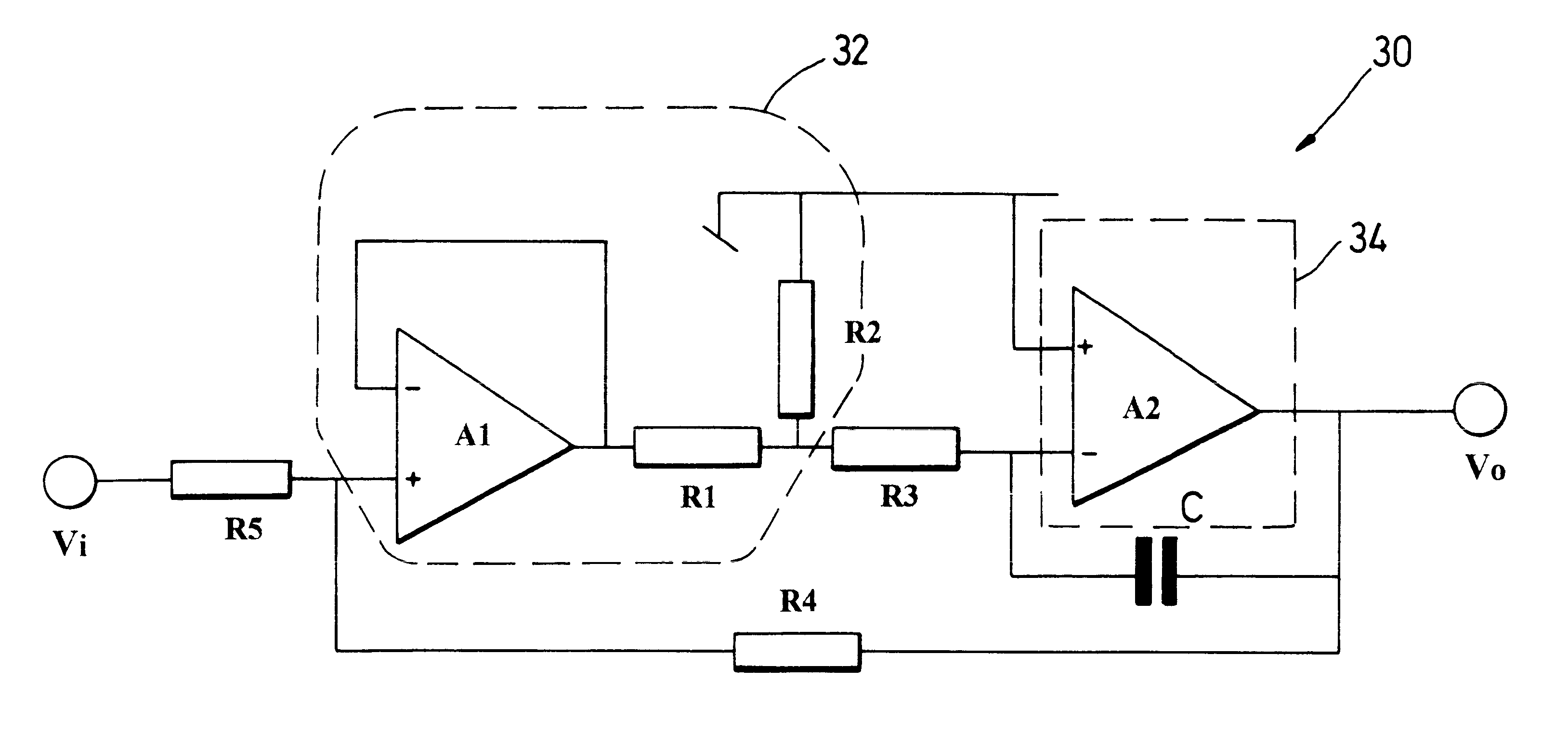
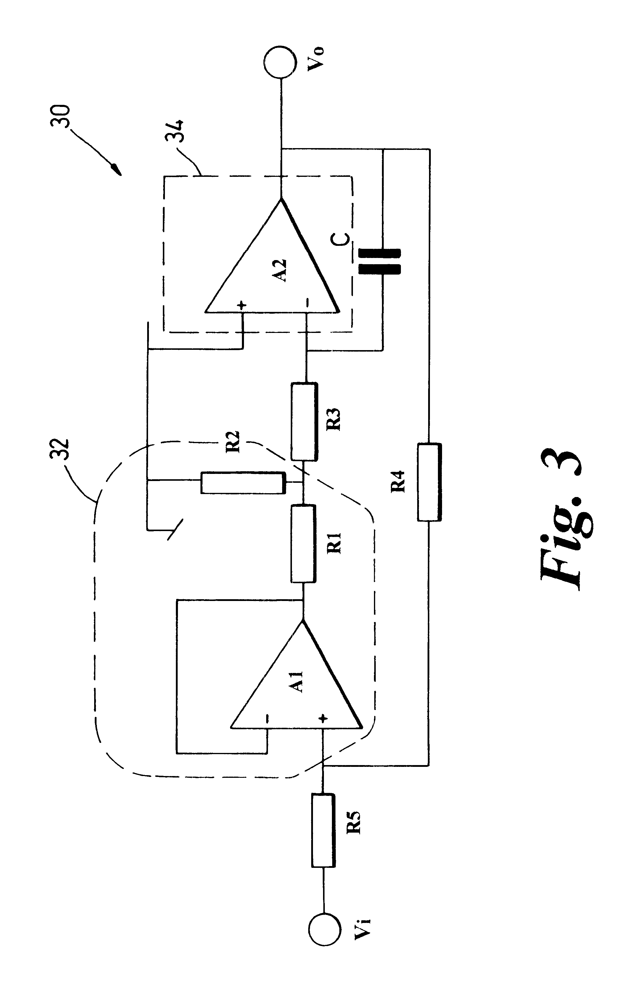
Applicant's co-pending application, U.S. Ser. No. 08 / 729,099 (Visocchi) the contents of which are incorporated herein, discloses a "modified" Miller Integrator circuit as schematically illustrated in FIG. 3 which has the potential to provide an enhanced time constant. The Miller Integrator circuit 30 as disclosed in U.S. Ser. No. 08 / 729,099 has a discrete component form comprising a combination of operational amplifiers (op-amps) and other discrete circuit components. Devices such as op-amps are readily available as standard "plug-in" components.

The circuit comprises first and second op-amps A1, A2. The output of the first op-amp A1 is connected by first and second resistors R1, R2 to ground and via the first and a third resistor R1, R3 to an inverting input of the second op-amp A2. The first op-amp A1 has a feedback connection between its output and its inverting input. The second op-amp A2 is configured as a Miller Integrator. The circuit is arranged with a feedback from the outpu...


PUM


Abstract

The present invention provides a long time constant integrator circuit as part of an integrated circuit. The integrator circuit is fully integrated on chip with no external capacitive or resistive components for enhancing the circuit's time constant. It achieves a -3 dB cut-off frequency of 1.6 Hz. The circuit is realisable on a very small area of silicon being formed by a bipolar process using npn transistors, resistive and capacitive elements. The integrator circuit comprises a transconductance stage as an input to an operational amplifier. The circuit design is fully differential and employs realisable resistors and capacitors.

Description

The present invention relates to a fully integrated long time constant integrator circuit which finds application in long time constant feedback loop arrangements such as control circuits in optical receivers.BACKGROUND TO THE INVENTIONThe ever increasing demands for high capacity communications systems has seen the wide spread employment of optical fibre networks across the world. A fundamental component for such systems is a means of converting optical pulses comprising a digital bit stream into electrical signals. This component of such a system is commonly known as an optical receiver.The operational requirements of such a receiver are very demanding. The receiver is required to exhibit a very low noise characteristic, such that it is capable of detecting very low levels of optical input in systems employing maximum optical fibre lengths, thus requiring high gain amplification for maximum sensitivity, but is conversely required to cope with high levels of optical input in system...

Claims


Application Information

Patent Timeline
IPC IPC(8): G06F7/64G06F7/60H03H11/04H03F3/70H03G3/30G06G7/186H03G5/02
CPCG06G7/186H03F3/087H03G3/3084H03G5/02
Inventor VISOCCHI, PASQUALINO MICHELLEWHITTAKER, EDWARD J WFLETT, ROBIN M
Owner NORTEL NETWORKS LTD
Why Eureka
Try Eureka