
Common rail for diesel engine

a diesel engine and common rail technology, applied in the direction of machines/engines, liquid fuel feeders, mechanical apparatus, etc., can solve the problems of fuel leakage, achieve the effect of increasing fatigue strength, reducing the degree of fatigue concentration, and increasing strength

Inactive Publication Date: 2002-12-17
USUI KOKUSAI SANGYO KAISHA LTD
View PDF22 Cites 32 Cited by
  • Summary
  • Abstract
  • Description
  • Claims
  • Application Information

AI Technical Summary

Benefits of technology

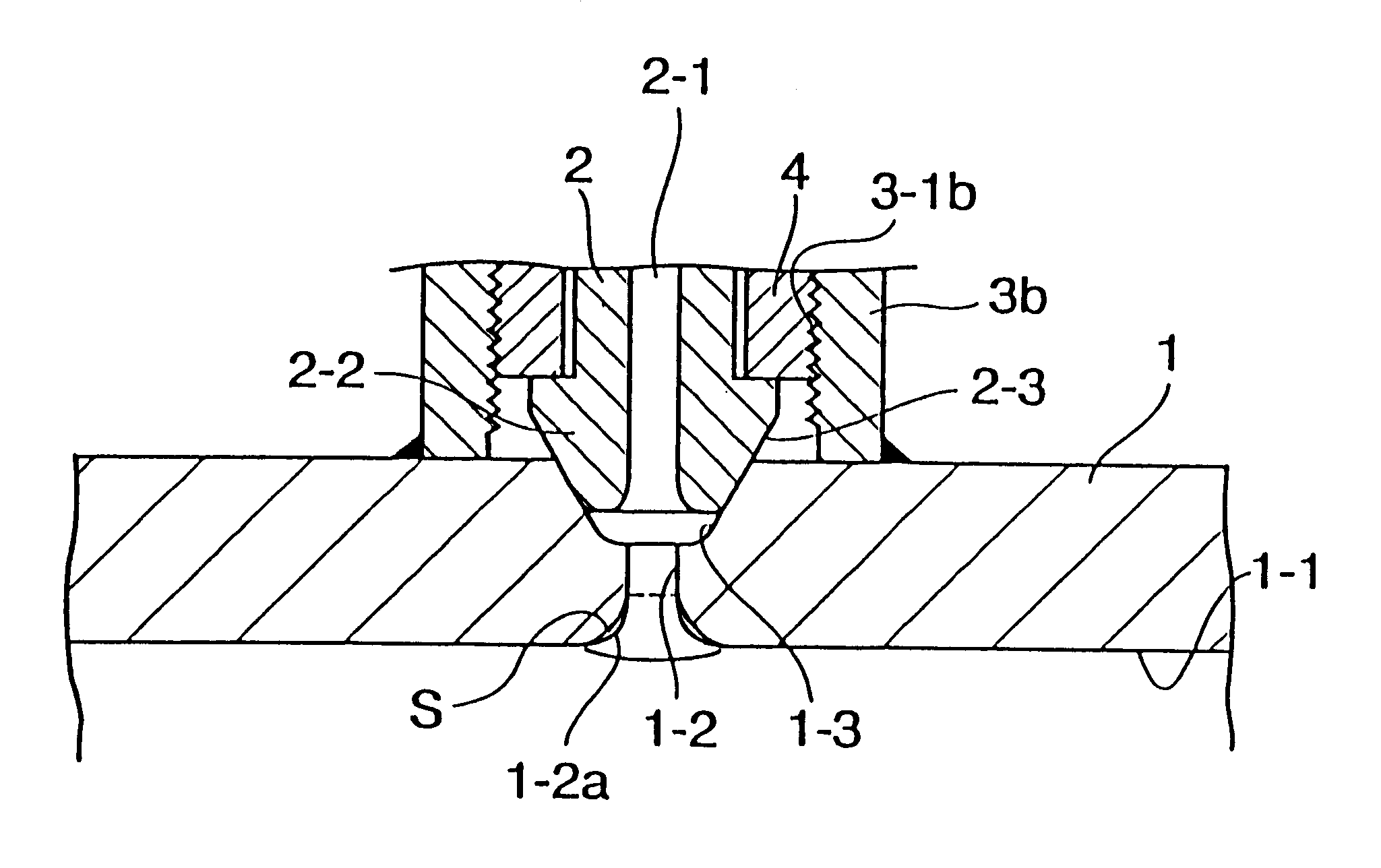
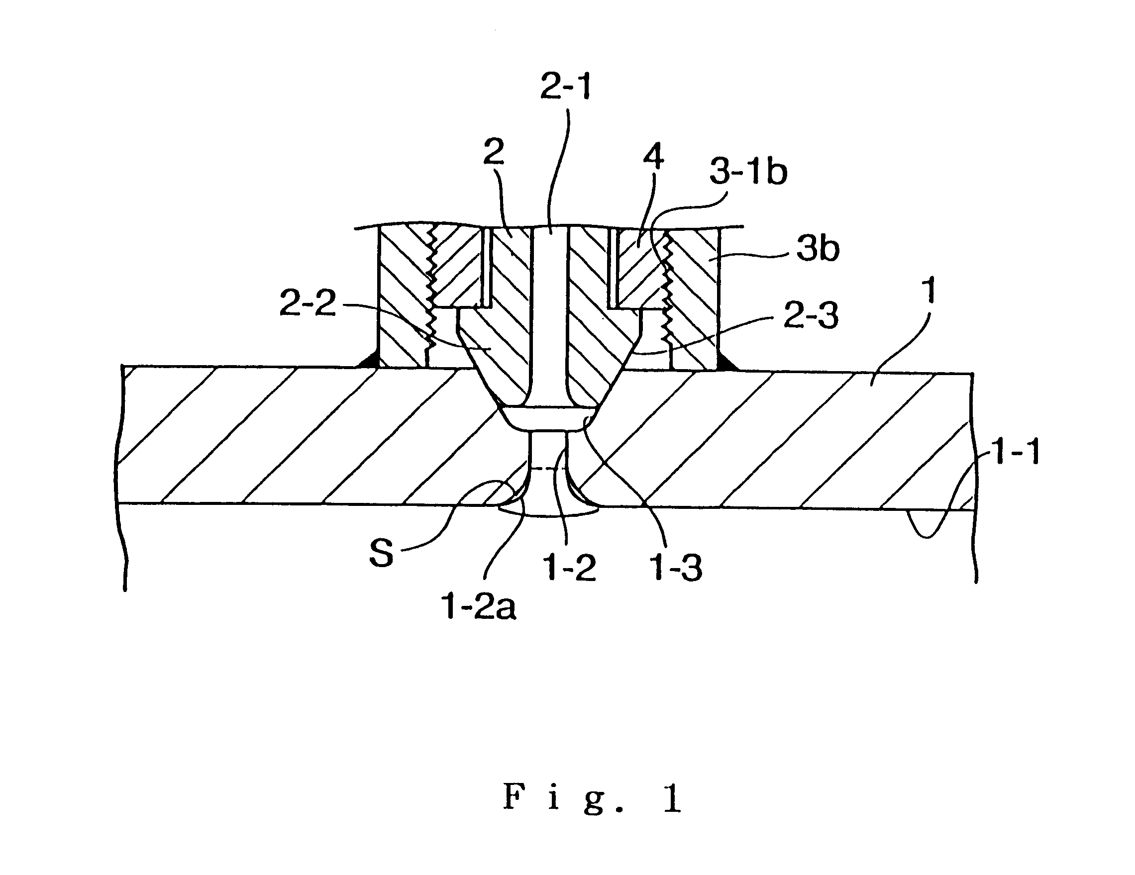
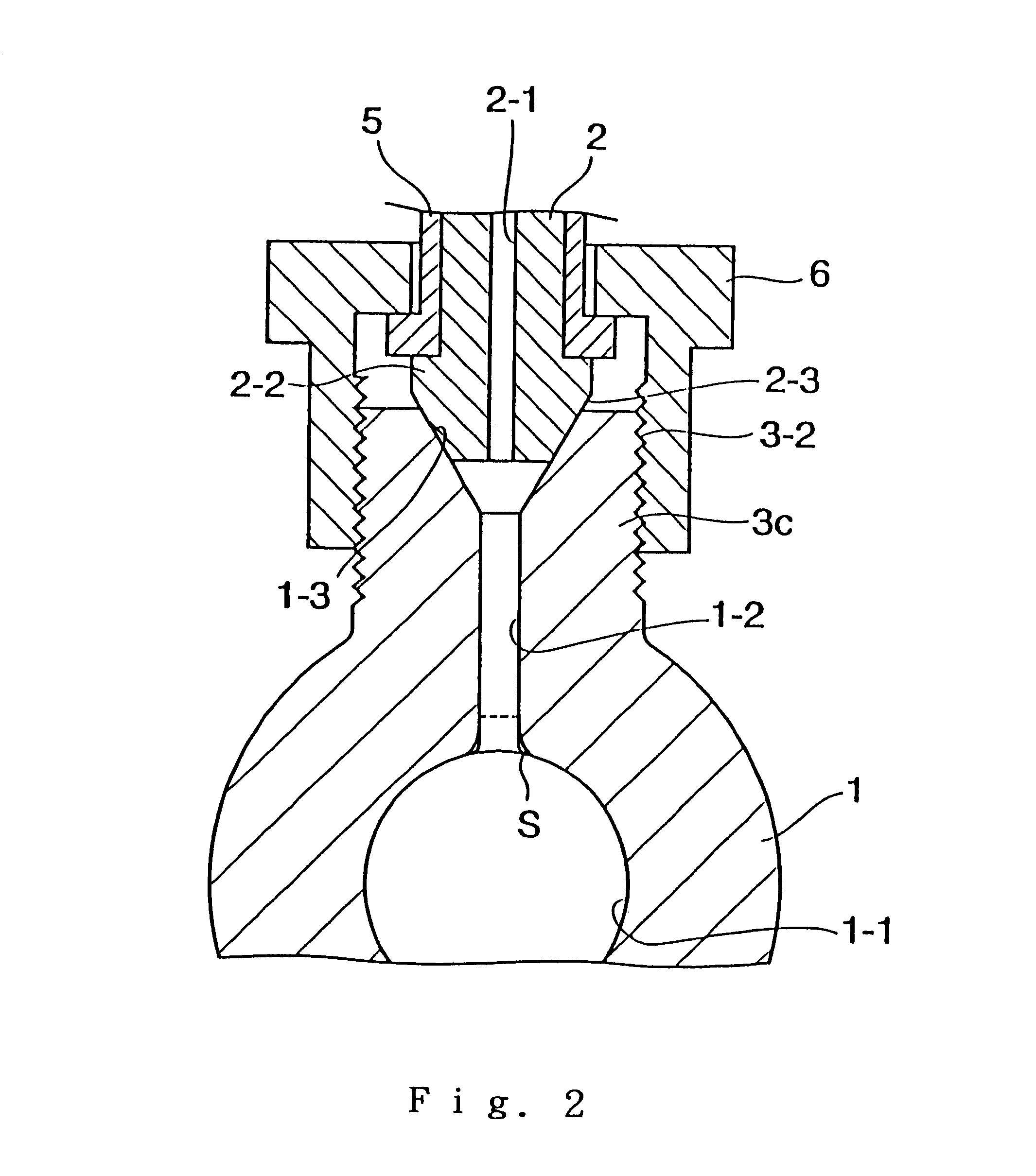
The invention has been made to solve the above-described problems of the prior art, and provides a common rail for a diesel engine in which fatigue strength against inner pressure can be increased by lowering the extent of concentration of stress which occurs in the portions of intersections of branch holes which include the inner peripheral edges of the lower ends of the respective branch holes 1-2 and a circulating passage of the main pipe rail, or in the branch holes, the inner circumferential surface of the main pipe rail or the like.
In the common rail for a diesel engine, in the case where the Ni-diffused fatigue strength reinforcing layer which is formed by heating the Ni layer plated in advance is formed in the portion of the surface or a surface portion of a parent metal where a nonmetal inclusion is present, the fatigue strength reinforcing layer formed by heating this Ni layer is larger in hardness and smaller in elongation than the parent metal, whereby the difference in hardness or elongation between a steel surface and the nonmetal inclusion in the surface or the surface layer of the parent metal becomes small. In the case where this fatigue strength reinforcing layer is formed in, for example, the portions of intersections of the branch holes and the circulating passage of the main pipe rail, the degree of concentration of fatigue stress which occurs in the portions of intersections of the branch holes and the circulating passage of the main pipe rail is lowered and the maximum value of stress which occurs in the intersection portions is lowered, whereby fatigue strength against inner pressure is improved. Incidentally, the thickness of the fatigue strength reinforcing layer is not limited to a particular value, but 10-30 .mu.m is appropriate for the fatigue strength reinforcing layer to serve its effect and advantage.
In the case where the Ni-diffused fatigue strength reinforcing layer S is formed in the above-described manner on the portion of intersection of the branch hole 1-2 which communicates with the circulating passage 1-1 of the main pipe rail 1 and the circulating passage 1-1 of the main pipe rail 1, or over the portion of intersection and the circulating passage 1-1 of the main pipe rail 11 or over the entire inner circumferential surface of the main pipe rail 1, the portion of intersection of the branch hole 1-2 and the circulating passage 1-1 or the portion of intersection and the circulating passage 1-1 of the main pipe rail 1 or the entire inner circumferential surface of the main pipe rail 1 increases in strength against inner pressure working on the main pipe rail 1, and the degree of stress concentration due to the nonmetal inclusion is reduced to a great extent. Accordingly, it is possible to substantially solve the problem that cracks occur from the portion of intersection of the branch hole 1-2 and the circulating passage 1-1, such as the opening edge portion P.
As described above, in accordance with the invention, in a common rail for a diesel engine which includes branch holes formed in an axial peripheral wall portion of a main pipe rail and branch connectors connected to the respective branch holes integrally or via separate connecting members, a. Ni-diffused fatigue strength reinforcing layer which is formed by heating a Ni layer plated in advance is formed in at least a portion of the inner circumferential surface of the common rail, such as the branch holes or the portions of intersections of the branch holes and a circulating passage of the main pipe rail. Accordingly, the increased strength and the action of the fatigue strength reinforcing layer make small the difference in hardness or elongation between a steel surface and a nonmetal inclusion occurring in the inner surface or the surface layer of a rail. thereby lowering the degree of fatigue concentration to increase fatigue strength against inner pressure. Consequently, the common rail for a diesel engine serves the superior advantage of being capable of performing reliable and stable functions with superior durability and without leakage of fuel due to occurrence of cracks.

Problems solved by technology

Cracks easily occur from the lower-end inner circumferential edge portion P, and there is a possibility that the cracks causes leakage of fuel.

Method used


Image

  • Common rail for diesel engine
  • Common rail for diesel engine
  • Common rail for diesel engine

Examples


Embodiment Construction

A 4-.mu.m-thick Ni plating layer was formed by electroplating over the portions of intersections of branch holes and a circulating passage of an S45C-made common rail formed by continuous forging (its main pipe rail was 24 mm.O slashed. in outer diameter, 10 mm.O slashed. in inner diameter and 3 mm.O slashed. in branch-hole diameter). The common rail was placed in an inert gas atmosphere heating furnace, and was heating at 1,130.degree. C. for 3 minutes and then quenched to form a Ni-diffused fatigue strength reinforcing layer of thickness about 18 .mu.m over the surface portion of the portions of intersections of the branch holes and the circulating passage.

When the fatigue limit of the common rail was examined with a repeated pressure testing machine, the following result was obtained. A comparative related art common rail of the same size which had no fatigue strength reinforcing layer over the portions of intersections of branch holes and a circulating passage was damaged by the...


PUM


Abstract

A common rail includes a main pipe rail having a circulating passage extending in its inside in the axial direction thereof, branch holes formed in an axial peripheral wall portion of the main pipe rail, and branch connectors connected to the respective branch holes integrally or via separate connecting members. A Ni-diffused fatigue strength reinforcing layer is formed by heating a Ni layer plated in advance on at least a portion of an inner circumferential surface of the common rail. The increased strength and the action of the fatigue strength reinforcing layer lowers the degree of fatigue concentration to increase fatigue strength against inner pressure.

Description

1. Field of the InventionThe present invention generally relates to a common rail such as a high-pressure fuel branch pipe or a block rail in an accumulated-pressure fuel injection system for a diesel internal combustion engine.2. Description of the Prior ArtsA number of constructions have heretofore been known in the field of this kind of diesel engine fuel injection pipe. In the construction shown in FIG. 6 by way of example, a main pipe rail 1 has a circulating passage 1-1 of circular cross section formed in a peripheral portion of the interior of the main pipe rail 1 as well as a branch hole 1-2 which communicates with the circulating passage 1-1, and the branch hole 1-2 is outwardly opened to form a pressure-receiving seat surface 1-3. A ring-shaped connecting fitting 3 is used to surround the outer circumferential portion of the main pipe rail 1 in the vicinity of the pressure-receiving seat surface 1-3. A branch pipe 2 which serves as a branch connector has a connecting head ...

Claims


Application Information

Patent Timeline
IPC IPC(8): F02M55/02F02M55/00F02M47/02
CPCF02M55/005F02M55/025F02M47/02
Inventor USUI, MASAYOSHIASADA, KIKUO
Owner USUI KOKUSAI SANGYO KAISHA LTD
Learn More