Method and system of magnetic recording and reproducing with ultra-high density

Inactive Publication Date: 2002-12-24
KLIMOVITSKY ALEXANDR M +1
View PDF4 Cites 6 Cited by
  • Summary
  • Abstract
  • Description
  • Claims
  • Application Information

AI Technical Summary

Benefits of technology

Allowability of micro miniaturization due to essential decrease of the conjugation surface between head and the magnetic media; possibility to build single-track and multi-track magnetic data storage devices together with elimination or essential simplification of head coordinate displacement mechanism;
Achievement of high-quality recording and reproducing, and also stability, reliability and longevity;
Binary "zero" lines are being formed between magnetic marks corresponding to logical "ones" and separate them eliminating magnetic field cross-talk between neighbouring marks in the tracks;

Problems solved by technology

If the air gap is very small (which is needed to get higher data recording density and higher frequency of the recorded data), then the magnetic energy extended outside the gap becomes very small and inefficient for utilization of the magnetizing force of the magnetic head on the data signal because maximum intensity vector of this force extends inside the gap along the average line of the magnetic circuit of the magnetic head.
However, using the induction method leads to contradictory results because decrease in speed leads to decrease of induced electromotive force level at recording, and the increase of frequency shifts dynamic range of the frequency characteristic.
This leads to increased surface wear due to contact friction between neighboring surfaces, and to loss of reliability of recording and reproducing quality (tribology problems), limits lifetime, lowers durability.
However, even the laser recording method is non-contact and has no friction with the recording surface, it still lacks the ease of re-recording.

Method used


Image

  • Method and system of magnetic recording and reproducing with ultra-high density
  • Method and system of magnetic recording and reproducing with ultra-high density
  • Method and system of magnetic recording and reproducing with ultra-high density

Examples


Embodiment Construction

The described method allowing to achieve ultra-high density of magnetic data is based on magnetic modulation interaction between magnetic head with magnetic medium having specific location format of magnetic marks and also specific features of magnetic head and the medium themselves.

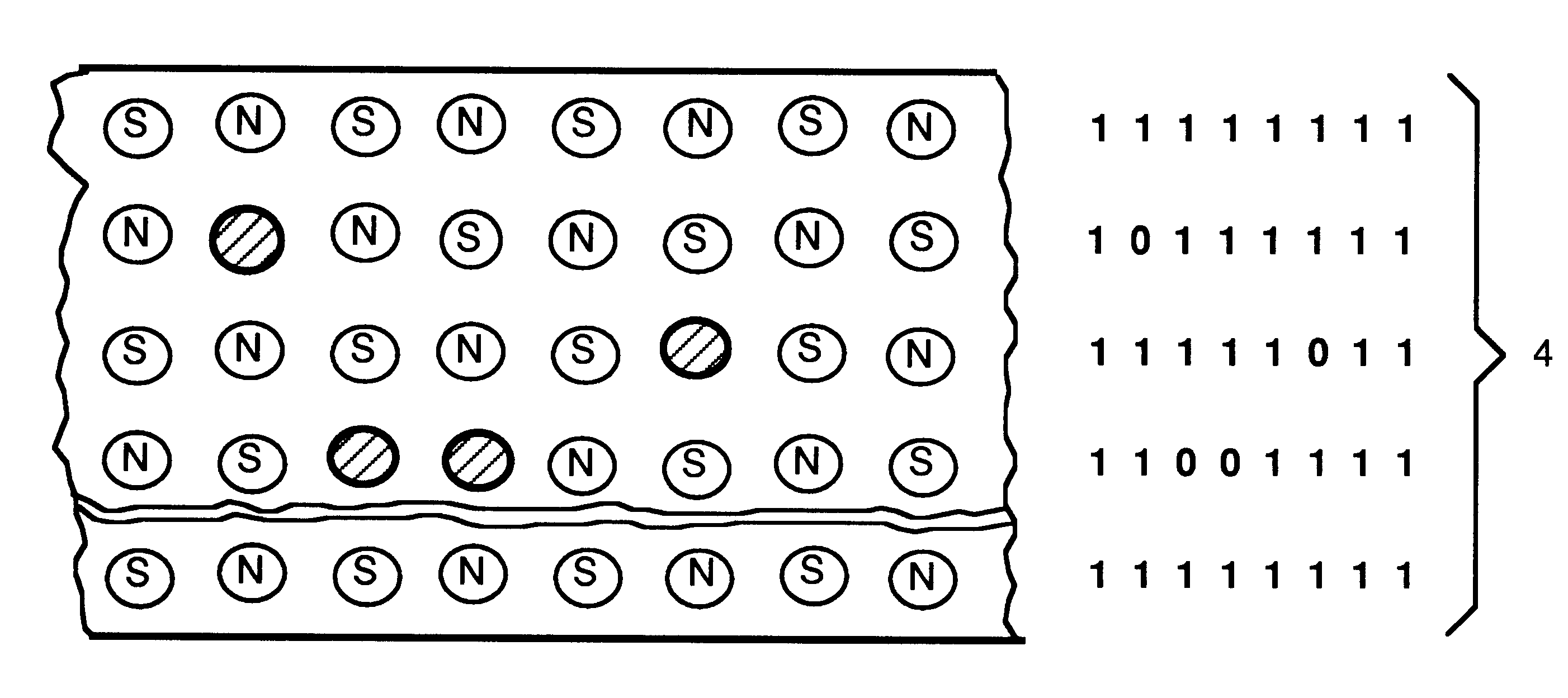
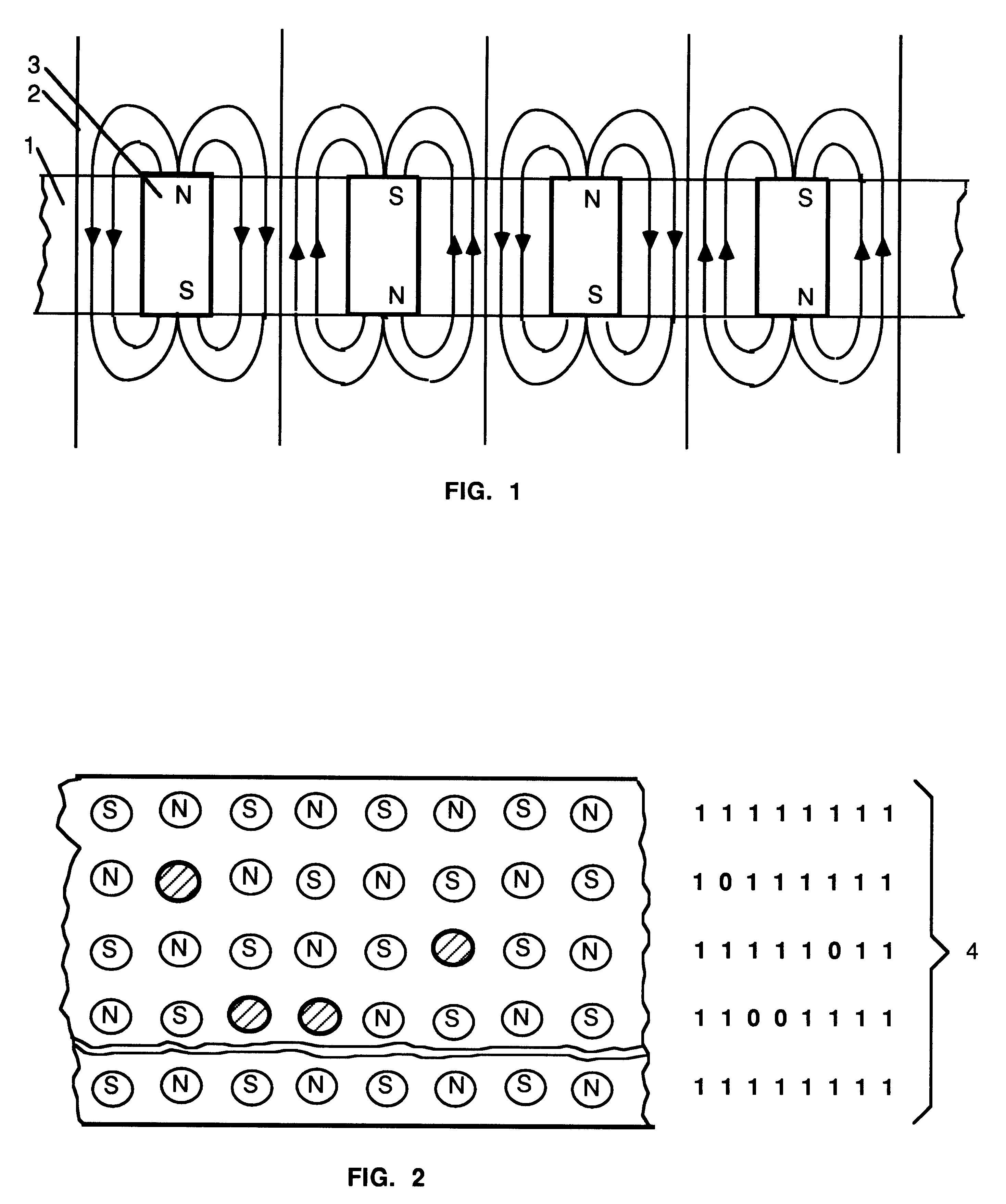
Recording of the magnetic marks 3 is to be done perpendicular to the plane of medium, so that neighbouring parallel marks corresponding to logical "ones" will have their magnetic axes orienting in the opposite directions (FIG. 1).

Magnetic marks corresponding to logical "zeros" remain un-magnetized at their corresponding locations at data track build of such "ones" and "zeros". Such "zero" marks remain un-magnetized at initial recording or demagnetized to zero level at repeated recordings.

Use of magnetic marks of different polarity allows to achieve zero levels of magnetic intensity lines 2 at meridian cross-sectional intervals between these neighbouring marks due to mutual compensation (subtraction) of o...


PUM


Abstract

Method and system of perpendicular magnetic recording and reproducing with ultra-high density for use in computer storage, audio, video recording euipment. Marks, as logical "1"-s are recorded at predeteremined distance from one another and their magnetic axes oriented in the opposite directions, as logical "0"-s are non-magnetized, forming pattern similar to chess-board order with the zero potential lines, eliminating crosstalk. Interaction "head-medium" is based on non-contact magnetic modulation, eliminating tribology problems. System may compose single or multi track medium, transporting linearly or rotating, with the immovable, quasi-immovable or scanning bi-polar or uni-polar magnetic heads, which have extremely small pointing conjugation area for interation with superminiature dimensions of magnetic fields of marks. System is realized by forming and recognizing the logical meaning of signals under checking of the strict general sequence different-directed alternation marks inside the tracks and in the neighboring tracks relatively of each other.

Description

This invention relates to field of magnetic recording and reproducing. It can be used in computer data storage devices, and devices for storing audio and video signals. Method and system of said magnetic recording and reproducing provide ultra-high degree of data density on various types of magnetic medium (magnetic tape, magnetic discs etc.). This method also allows building single-track and multi-track memory devices.BACKGROUND OF INVENTIONProcess of magnetic recording and reproducing can be of two types:A. Applying magnetic marks in parallel to the plane of magnetic medium (longitudinal in audio systems and computers; transverse and helical in video systems), andB. Applying magnetic marks perpendicular to this plane.Induction method known in the art is being used most widely. This method has several limitations, among them the following:1. Part of the field extended from air gap of the magnetic head is used for recording. It is done by convexing of the leakage flux extended from ...

Claims


Application Information

Patent Timeline
IPC IPC(8): G11B5/09G11B5/335G11B5/33G06K19/06G11B5/00G11B5/008G11B5/012G11B5/62
CPCG06K19/06187G11B5/09G11B5/33G11B5/335G11B5/00813G11B5/012G11B5/62G11B2005/0002G11B2005/0005
Inventor KLIMOVITSKY, ALEXANDR M.KLIMOVITSKY, VLADIMIR A.
Owner KLIMOVITSKY ALEXANDR M
Why Eureka
Try Eureka