
Continuous casting process for producing low carbon steel strips and strips so obtainable with good as cast mechanical properties

a casting process and low carbon steel technology, applied in the field of low carbon steel strip production, can solve the problems of less unity of the whole installation from the casting machine to the coiling reel, higher energy consumption, and further installations, and achieve good weldability and strength. good combination of ductility

Inactive Publication Date: 2003-01-07
ACCIAI SPECIALI TERNI SPA +1
View PDF9 Cites 28 Cited by
  • Summary
  • Abstract
  • Description
  • Claims
  • Application Information

AI Technical Summary

Benefits of technology

Therefore, an object the present invention is to provide a process for the production of low carbon steel strips having, as cast, a good combination of strength and ductility and a good weldability, without undergoing rolling and / or thermal cycling stages.
Another object of the present invention is to provide a carbon steel strip which has, as cast, improved mechanical properties, in particular a relatively low yield / fracture stress ratio and a continuous pattern of the tension-strain curve, in order to make the material particularly suitable for cold molding applications such as bending and drawing.
In the process of the present invention, the phase transformation features of coarse grain austenite, which formed during the continuous casting process without performing hot rolling and / or in line normalizing, are exploited to produce by a controlled cooling and coiling, predetermined volume divisions of the microstructure constituents in the material as cast in low carbon steels. These final microstructures, constituted by equiaxed ferrite, acicular ferrite and / or bainite, provide a typical stress-strain diagram, of the material, with a continuous pattern, having an improved deformability as to make the strip particularly suitable for the applications in cold molding.
Further trials conducted according to the process described in the present invention showed that it is possible to exploit the larger distribution and concentration uniformity of the alloy components in cast strips with a high solidification speed (low entity of the segregation) in order to homogenize the distribution of the microstructures and to avoid the formation of undesired structures, of the martenistic type, reducing the ductility and the formability of the material.
Furthermore, the inventors observed how the addition of elements such as vanadium and niobium, increased the hardenability of austenite and delayed the formation of equiaxed ferrite, easing the development of acicular ferrite and bainite. Furthermore, niobium and titanium, forming carbon-nitrides, inhibit the dimensional growth of the austenitic grains in high temperature heating processes, ensuring, for example, a better ductility in the thermally altered area of a welding.

Problems solved by technology

However, the above mentioned processes require further installations and higher energy consumption (e.g. rolling lines, furnace for intermediate heating etc.) and usually require larger space, and therefore less unity of the whole installation from the casting machine to the coiling reel.
Furthermore, the object of the processes aim at the thickness of the final structure of the strip, trying to make it as similar as possible to that of a hot rolled strip from a conventional cycle, and they do not teach how to obtain a product with the desired mechanical and technological properties, by exploiting the peculiarities of the phase transformation features for the as cast steels with big austenitic grain (usually 150-400 microns).

Method used


Image

  • Continuous casting process for producing low carbon steel strips and strips so obtainable with good as cast mechanical properties
  • Continuous casting process for producing low carbon steel strips and strips so obtainable with good as cast mechanical properties
  • Continuous casting process for producing low carbon steel strips and strips so obtainable with good as cast mechanical properties

Examples


example 2

Other strips having a thickness of 2.0-2.5 mm were obtained with the process of the present invention, by using the B and C types of steel of table 1, having a higher carbon content (0.052% and 0.09%, respectively).

The main cooling and coiling conditions are shown in table 4, together with some microstructure features of the strips so obtained. The mechanical properties of the strips and the Erichsen index, measure of the cold formability of the materials, are reported in table 5.

In FIGS. 7 and 8 the typical microstructures respectively of the strips 7 (steel B) and 14 (steel C), as observed through an optical microscope, are shown. Also in this case, by exploiting the phase transformation features of the coarse austenitic grain steels, it is possible to obtain mixed structures containing equiaxed ferrite and also acicular ferrite and bainite. The strength values are higher than those shown in example 1, relating to steel having 0.035% C, and ductility and cold formability remain at...

example 3

In this comparative example, the microstructures and the mechanical properties of a strip having a thickness of 2 mm and obtained with the steel of the D type (table 1) produced with a traditional cycle and comparing with those of a strip as cast, having the same chemical analysis, produced according to the process of the present invention, are reported. Clearly, the microstructure of the traditional strip is constituted by thin grains of polygonal ferrite and by perlite (FIG. 9), with a tensile stress diagram of a discontinuous pattern (FIG. 10). The typical mechanical properties of this conventional strip are shown in table 6. The use of relatively low coiling temperatures (table 7), with the process of the present invention allows the use of materials with acicular structures of the type as shown in FIG. 11, which are characterized by similar values of fracture stress, with a continuous pattern yield diagram (FIG. 12), and therefore with a lower yield / fracture stress ratio (table...

example 4

Some strips obtained according to the process of the present invention and made by the A and B types of steels, were pickled and underwent weldability trials. The point resistance welding trials were performed with electrodes having a diameter of 8 mm, adopting a stress of 650 kg, and by varying the current. In FIGS. 13a and 13b the diagrams that at the "number of cycles-current intensity" level provide weldability lobes, i.e. the field wherein the steel sheets are weldable without problems, are respectively shown. The comparison with a pickled sheet-steel having similar thickness, in low carbon steel obtained by a conventional production cycle (FIG. 14), shows how the strips obtained with the process of the present invention keep good weldability features, as to indicate an acceptable superficial state.

TABLE 2

TABLE 3

TABLE 4

TABLE 5

TABLE 6

TABLE 7

TABLE 8


PUM

PropertyMeasurementUnit
Temperatureaaaaaaaaaa

Abstract

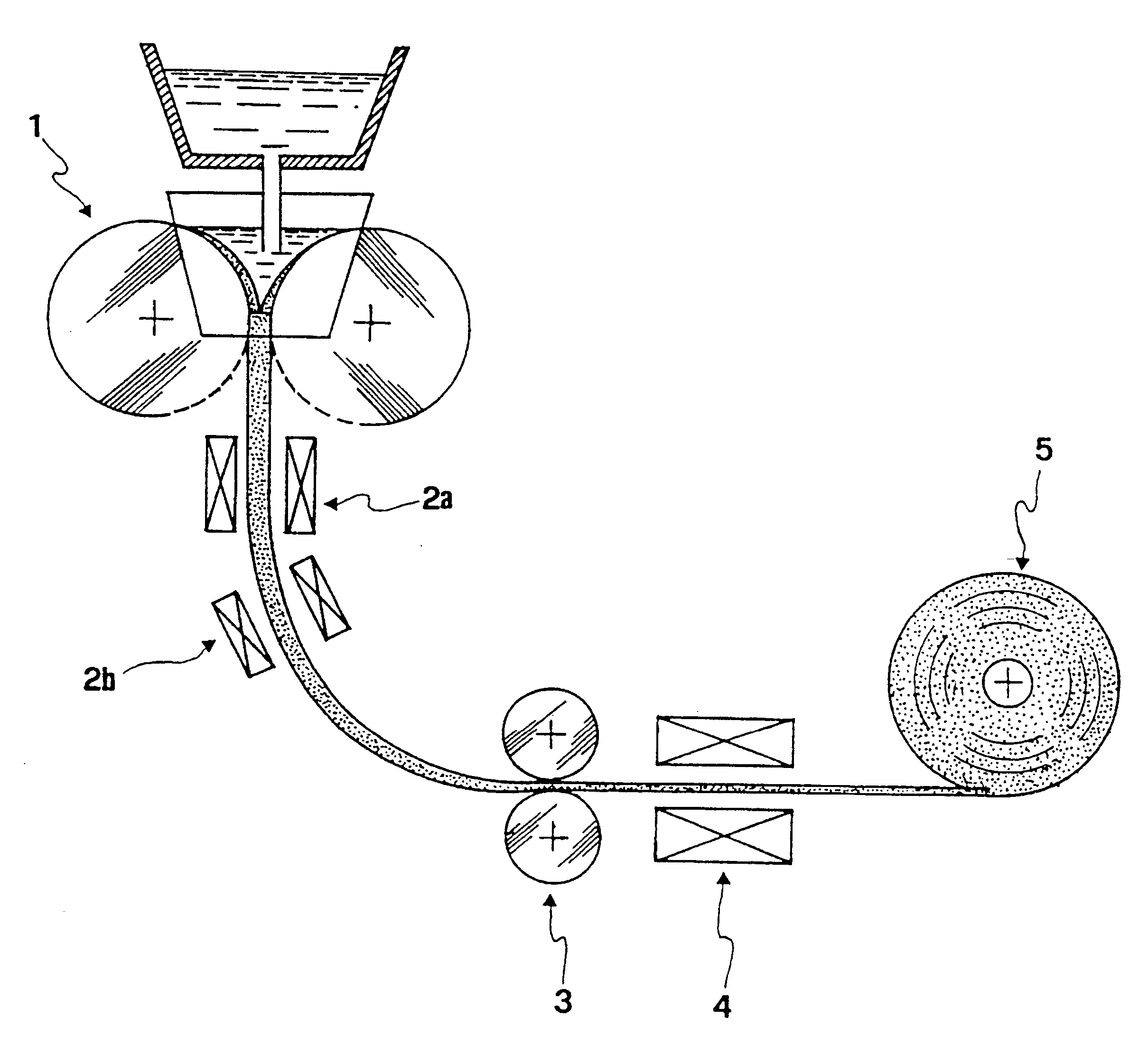
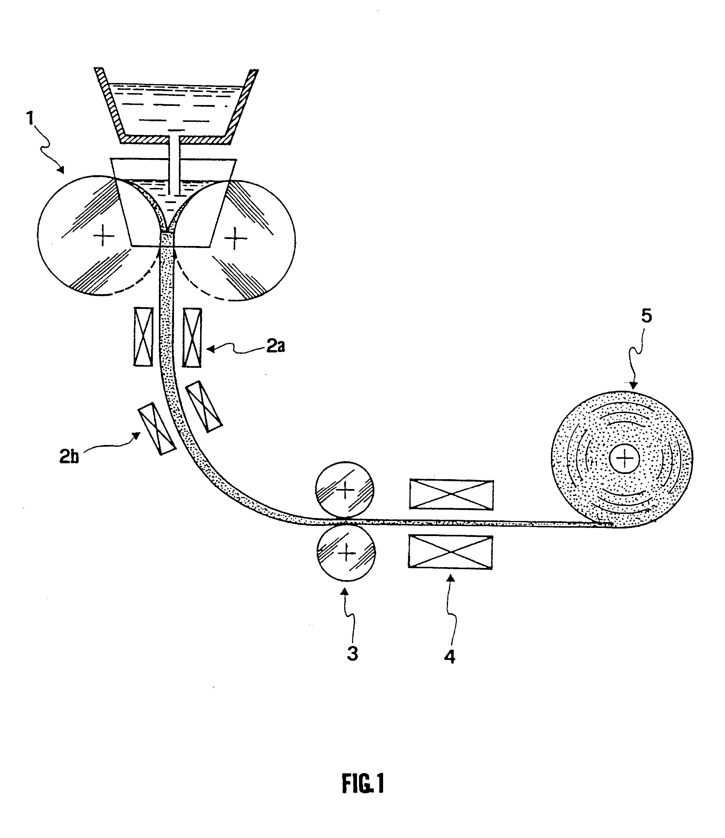
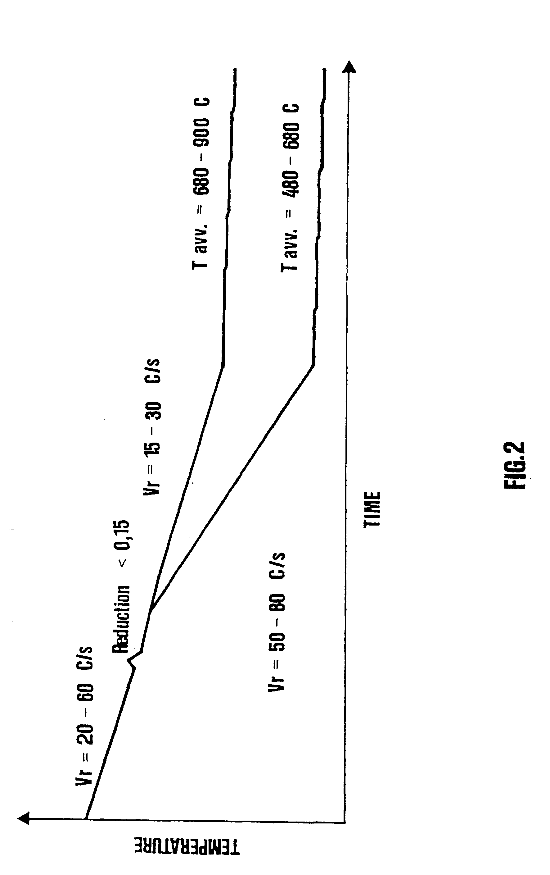
A process for the production of low carbon steel strips having a good combination of strength an formability, as cast, and a good weldability after the pickling by usual processes, comprising the following steps: casting, in a twin rolls continuous casting machine (1) comprising pinch rolls (3), a strip with a thickness comprised between 1 and 8 mm, having the following composition as weight percentage of the total weight: C 0.02-0.10; Mn 0.1-0.6; Si 0.02-0.35; Al 0.01-0.05; S<0.015; P<0.02; Cr 0.05-0.35; Ni 0.05-0.3; N 0.003-0.012; and, optionally, Ti<0.03; V<0.10; Nb<0.035, the remaining part being substantially Fe; cooling the strip in the area comprised between the casting-rolls and the pinch rolls (3); hot deforming the strip cast through said pinch rolls (3) at a temperature comprised between 1000 and 1300° C. until reaching a thickness reduction less than 15%, in order to encourage the closing of the shrinkage porosites; cooling the strip at a speed comprised between 5 and 80° C. / s down to a temperature (Tavv) comprised between 500 and 850° C.; and coiling into a reel (5) the so obtainable strip.

Description

The present invention refers to a process for the production of low carbon steel strips, having a good combination of strength and cold formability, as cast.Different methods for producing carbon steel strips through twin roll continuous casting devices are already known. These methods aim at the production of carbon steel strips having good properties of strength and ductility.In particular, in EP 0707908 A1 a twin roll continuous casting apparatus is shown and wherein a carbon steel strip is cast, for then undergoing in a hot rolling line with a 5-50% reduction of its thickness and being successively cooled. The flat thin product so obtained has good properties of strength and ductility thanks to the reduction in the grain dimension obtained with the hot rolling.From WO 95 / 13155 an in line thermical treatment for cast carbon steel strips aiming at the control of a strip microstructure as cast is shown. In particular, the cast strip is cooled below the temperature wherein the trans...

Claims


Application Information

Patent Timeline
IPC IPC(8): B22D11/06B22D11/00B22D11/124B22D11/128
CPCB22D11/0622C21D8/0215C21D8/0226C21D8/0263C22C38/40C22C38/001C22C38/02C22C38/04C22C38/06C21D2211/005C21D2211/009B22D11/06
Inventor MASCANZONI, ANTONIOANELLI, ETTORE
Owner ACCIAI SPECIALI TERNI SPA
Learn More