Alternator

a technology of alternators and rotating parts, applied in the field of alternators, can solve problems such as significant decrease of operability, deterioration of output, and deterioration of outpu

Inactive Publication Date: 2003-01-07
MITSUBISHI ELECTRIC CORP
View PDF36 Cites 69 Cited by
  • Summary
  • Abstract
  • Description
  • Claims
  • Application Information

AI Technical Summary

Problems solved by technology

In the conventional stator coil 52, because clamping area is required for the jig, making the coil ends high, there has been a problem of increased coil end leakage reactance, causing output to deteriorate.
Furthermore, if the number of claw-shaped magnetic poles and the number of slots are increased, the coils in the coil ends are closer together, and when the joining portions of the conductor segments expand, because the space between the coils in the coil ends become excessively narrow and the height of the coil ends is increased, there is mutual interference between the coils in the coil ends, and there has been a problem of deterioration in output.
Furthermore, in the conventional stator 50, a large number of the short conductor segments 54 must be inserted into the stator core 51 and their end portions 54b must be joined by welding, soldering, etc., which has led to a problem of significantly decreased operability.
In addition, when joining the end portions 54b, there has also been a problem of short circuiting often occurring between the joint portions due to spilt solder or weld melt, significantly decreasing mass-productivity.
Furthermore, in the conventional stator construction which uses conductor segments 54, because buckling, etc., occurs more frequently during insertion of the conductor segments 54 into the slots as the number of slots increases, it has been difficult to apply this construction to an alternator aiming for compactness and high output by increasing the number of claw-shaped magnetic poles and the number of slots.
Furthermore, there has been a problem of decreased reliability of the conventional stator 50 constructed in this manner because of the problems explained below.
First, because the front-end coil end groups are constructed such that the joint portions between the end portions 54b where the insulation coating has been lost due to welding and soldering are arranged in rows in a circumferential direction, the coil-end construction becomes susceptible to corrosion through exposure to moisture and the ability to withstand corrosion is extremely low.
Furthermore, because the coil ends are constructed from ninety-six joining portions in two rows, that is from 192 joining portions, the construction is susceptible to short circuiting, and short-circuiting accidents happen easily.
However, in this construction, although the fifth and seventh magnetomotive harmonic frequencies of the stator can be reduced, one problem has been that the eleventh and thirteenth magnetomotive harmonic frequencies of the stator, which occupy a large ratio among the magnetic flux pulsation which arise in the alternator, are increased, decreasing the effective reduction in magnetic noise.
Furthermore, if the number of claw-shaped magnetic poles and the number of slots are increased in order to achieve compactness and high output, pulsation in magnetic flux occurring between the teeth and the claw-shaped magnetic poles increase, and at the same time because the rigidity of the stator is decreased by the reduction in the width of the teeth, magnetic noise tends to be promoted.
Consequently, with the magnetic counter-measures in which two three-phase coils are wound into the slots such that their positions are offset by an electrical phase difference of 30.degree., another problem has been that it is not possible to sufficiently reduce magnetic noise in an alternator achieving compactness and high output.

Method used


Image

  • Alternator
  • Alternator
  • Alternator

Examples


embodiment 1

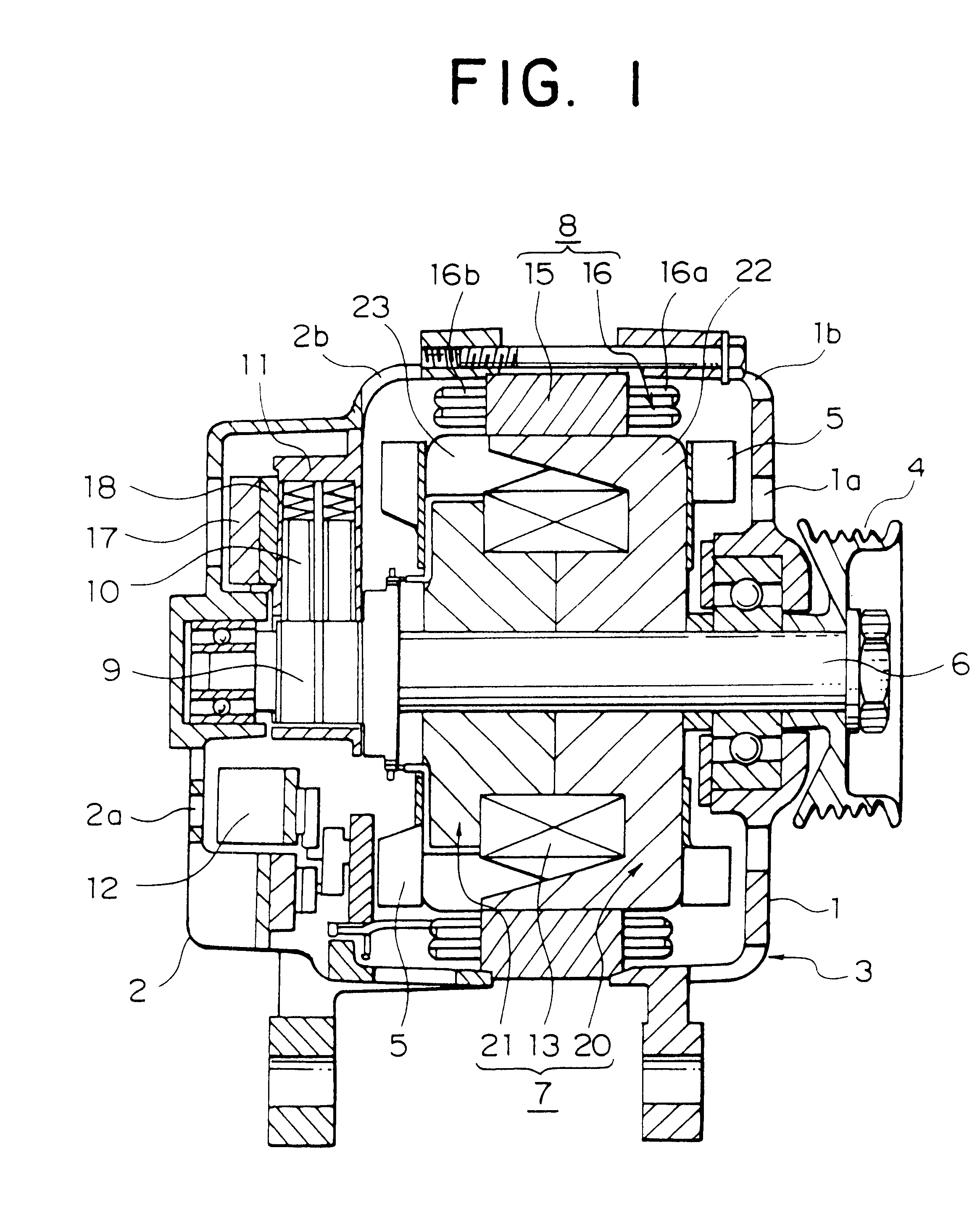
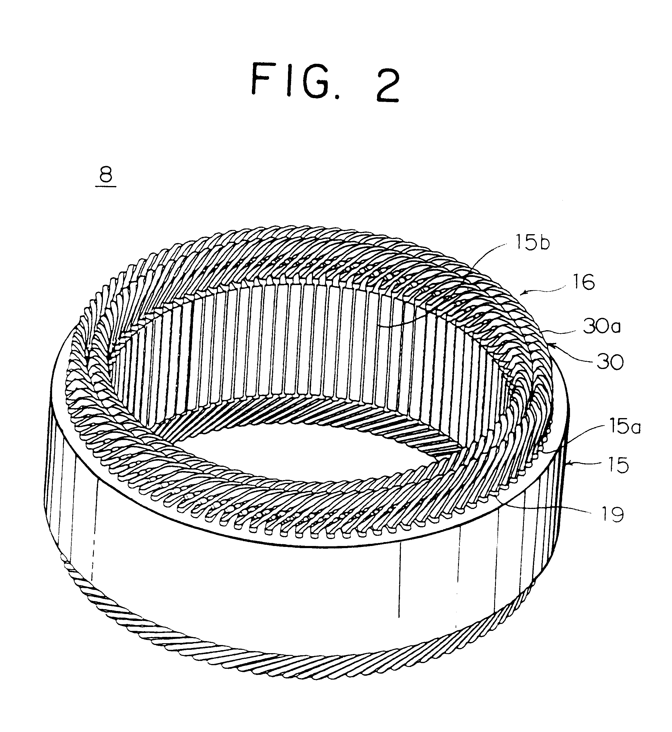
FIG. 1 is a cross section showing a construction of an automotive alternator of the present invention, FIG. 2 is a perspective showing a stator of this automotive alternator, FIG. 3 is an end elevation explaining connections in one stator coil phase portion in this automotive alternator, FIG. 4 is a circuit diagram for this automotive alternator, FIGS. 5 and 6 are diagrams explaining the manufacturing process for wire-strand groups constituting part of the stator coil used in this automotive alternator, FIGS. 7A and 7B are an end elevation and a plan, respectively, showing an inner-layer wire-strand group constituting part of the stator coil used in this automotive alternator, FIGS. 8A and 8B are an end elevation and a plan, respectively, showing an outer-layer wire-strand group constituting part of the stator coil used in this automotive alternator, FIG. 9 is a perspective showing part of a strand of wire constituting part of the stator coil used in this automotive alternator, FIG...

embodiment 2

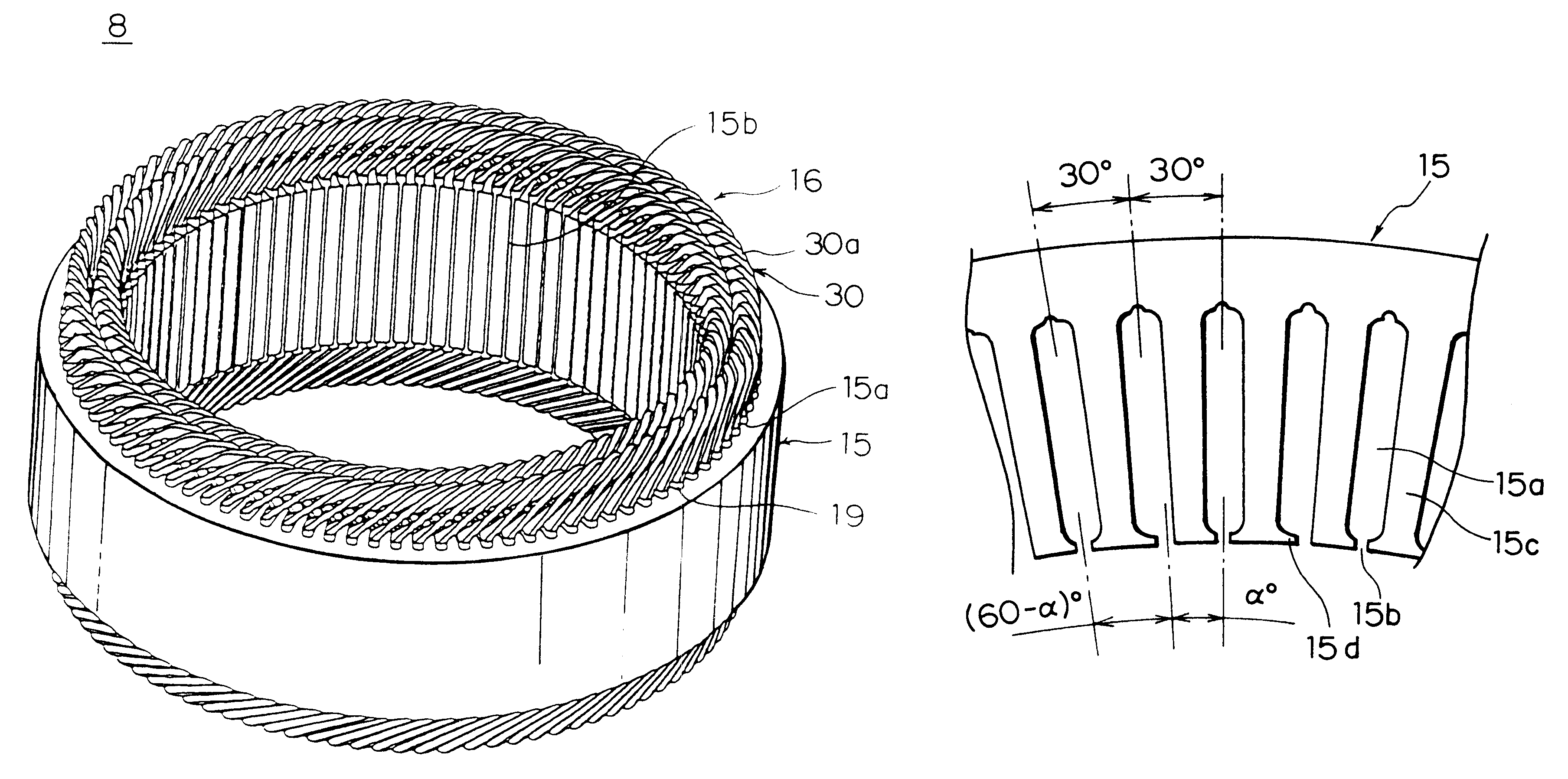
In Embodiment 2 of the present invention, because the phase difference between the phases in each of the three-phase coils 160 does not change, there is no decrease in output. Furthermore, because the two three-phase coils 160 are disposed so as to have a mutual phase difference corresponding to an electrical angle of (60-.alpha.).degree. and the circumferential air-gap centers of the adjacent slot opening portions 15b have a non-uniform pitch so as to alternate between an electrical angle of .alpha..degree. and an electrical angle of (60-.alpha.).degree., the higher harmonic components of the magnetomotive force which are the cause of electromagnetic noise can be reduced. Thus, by using the construction of Embodiment 2 of the present invention, a sufficient level of noise reduction can be achieved even in an automotive alternator having compactness and high output where magnetic noise is promoted by an increased number of claw-shaped magnetic poles and slots.

Furthermore, by changin...

embodiment 3

In Embodiment 3, as shown in FIG. 17, by adjusting a circumferential width of the teeth 15c, circumferential air-gap centers of adjacent slot opening portions 15b are disposed at a non-uniform pitch so as to alternate between an electrical angle of .alpha..degree. and an electrical angle of (60-.alpha.).degree.. Thus, the circumferential air-gap centers of the slots 15a are arranged so as to alternate between an electrical angle of .alpha..degree. and an electrical angle of (60-.alpha.).degree.. Thus, .alpha..noteq.30.

Moreover, the rest of the construction is the same as in Embodiment 2 above.

In Embodiment 3, because the pitch between the circumferential air-gap centers of the adjacent slots 15a is arranged so as to alternate between an electrical angle of .alpha..degree. and (60-.alpha.).degree., the phase difference between the phases in each of the three-phase coils 160 does not change. Furthermore, the two three-phase coils 160 are arranged so as to have a mutual phase differenc...


PUM


Abstract

An alternator includes a stator having an annular stator core provided with a number of slots extending axially disposed in lines circumferentially so as to open on an inner circumferential side and a stator coil wound into the stator core so as to be installed in the slots, a rotor having a number of claw-shaped magnetic poles for alternately forming north-seeking (N) and south-seeking (S) poles about a rotational circumference, the rotor being rotatably disposed on the inner circumferential side of the stator core, a bracket supporting the rotor and the stator, and a rectifier disposed at a first axial end of the stator and connected to end portions of the stator coil, the rectifier converting alternating current from the stator coil into direct current, wherein a number of slots is two per phase per pole, and the stator coil comprises a number of winding sub-portions in each of which a long strand of wire is wound so as to alternately occupy an inner layer and an outer layer in a slot depth direction within the slots at intervals of a predetermined number of slots by folding back the strand of wire outside the slots at axial end surfaces of the stator core.

Description

1. Field of the InventionThe present invention relates to an alternator driven by an internal combustion engine, for example, and in particular, relates to a stator construction for an automotive alternator mounted to an automotive vehicle such as a passenger car or a truck.2. Description of the Related ArtFIG. 18 is a side elevation showing part of a stator of a conventional automotive alternator such as described in Japanese Patent No. 2927288, for example, FIG. 19 is a perspective showing a conductor segment used in the stator of the conventional automotive alternator shown in FIG. 18, and FIGS. 20 and 21 are perspectives from a front end and a rear end, respectively, of part of the stator of the conventional automotive alternator shown in FIG. 18.In FIGS. 18 to 21, the stator 50 includes: a stator core 51; a stator coil 52 wound into the stator core 51; and insulators 53 mounted inside slots 51a, the insulators 53 insulating the stator coil 52 from the stator core 51. The stator...

Claims


Application Information

Patent Timeline
Patent Type & Authority Patents(United States)
IPC IPC(8): H02K3/28H02K3/12H02K9/06H02K3/50H02K1/16H02K9/04H02K15/06H02K15/00H02K15/04H02K15/02H02K19/22
CPCH02K3/12H02K3/50H02K3/28H02K2203/09H02K15/02
Inventor ASAO, YOSHIHITOFUJITA, MASAHIKOADACHI, KATSUMI
Owner MITSUBISHI ELECTRIC CORP
Why Eureka
Try Eureka