

Apparatus for electrical stimulation of the body
a technology of electrical stimulation and apparatus, applied in the field of apparatus for electrical stimulation of the body, can solve the problems of reducing the distance that users can walk, difficulty in ground clearance, and rapid fatigu
- Summary
- Abstract
- Description
- Claims
- Application Information
AI Technical Summary
Benefits of technology
Problems solved by technology
Method used
Image

Examples
Embodiment Construction
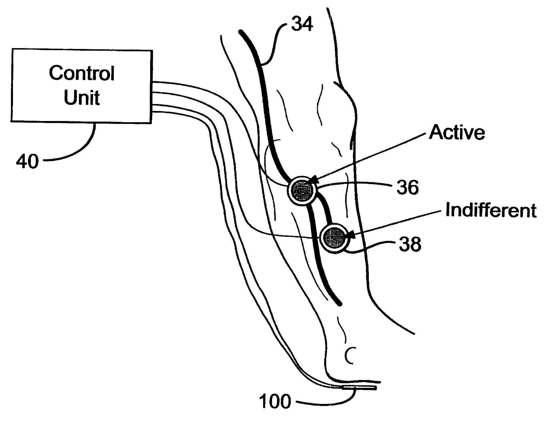
The apparatus disclosed in the drawings is an electronic device designed to assist people who have a dropped foot due to neurological damage that inhibits walking. As previously explained, a dropped foot, the inability to lift a foot whilst walking, resulting in the foot being dragged forward or swung out to the side, is a common disability following neurological injury. By stimulating the common peroneal nerve at its most superficial point, passing over the head of the fibula bone, it is possible through excitation of the withdrawal reflex to cause dorsiflexion with degrees of hip and knee flexion. If this is timed with walking using a foot switch worn in the shoe, walking can be significantly improved. The stimulus gives rise to a sensation like "pins and needles" and the patient soon becomes used to it. The apparatus can be made about the same size as a stack of playing cards, and it can be worn in the pocket or on a belt clip. Wires worn under the clothing carry the electrical s...
PUM
 Abstract
Description
Claims
Application Information